
Ultimate Guide to Data Center Power Redundancy
Power redundancy is the backbone of data center reliability. Without it, a single failure - like a UPS malfunction or generator issue - could disrupt operations, causing downtime and financial losses. Between 2019 and 2022, 80% of data centers experienced outages, with 60% costing over $100,000 and 15% exceeding $1 million. Here's what you need to know:
- What It Is: Power redundancy means duplicating critical electrical systems (UPS, generators, PDUs) to keep operations running during failures or maintenance.
- Key Benefits: Improved uptime, fewer disruptions, and operational flexibility. For example, Tier IV data centers achieve 99.995% uptime, limiting downtime to just 26.3 minutes annually.
- Redundancy Levels: Configurations like N, N+1, 2N, and 2N+1 offer varying levels of reliability. Higher levels (e.g., 2N+1) provide fault tolerance but come at a higher cost.
- Tier Standards: Data centers are classified into four tiers (I-IV) based on redundancy and uptime, with Tier IV offering the highest fault tolerance.
- Critical Components: Systems like UPS, backup generators, and dual utility feeds ensure uninterrupted power delivery.
The right redundancy setup depends on your workload's criticality and budget. Higher tiers and configurations like 2N+1 are ideal for mission-critical systems, while less critical workloads can opt for simpler setups. Investing in redundancy minimizes risks and ensures uninterrupted operations.
Data Center Redundancy Explained: N, N+1, and 2N Systems
sbb-itb-501186b
Uptime Tier Standards and Redundancy Requirements
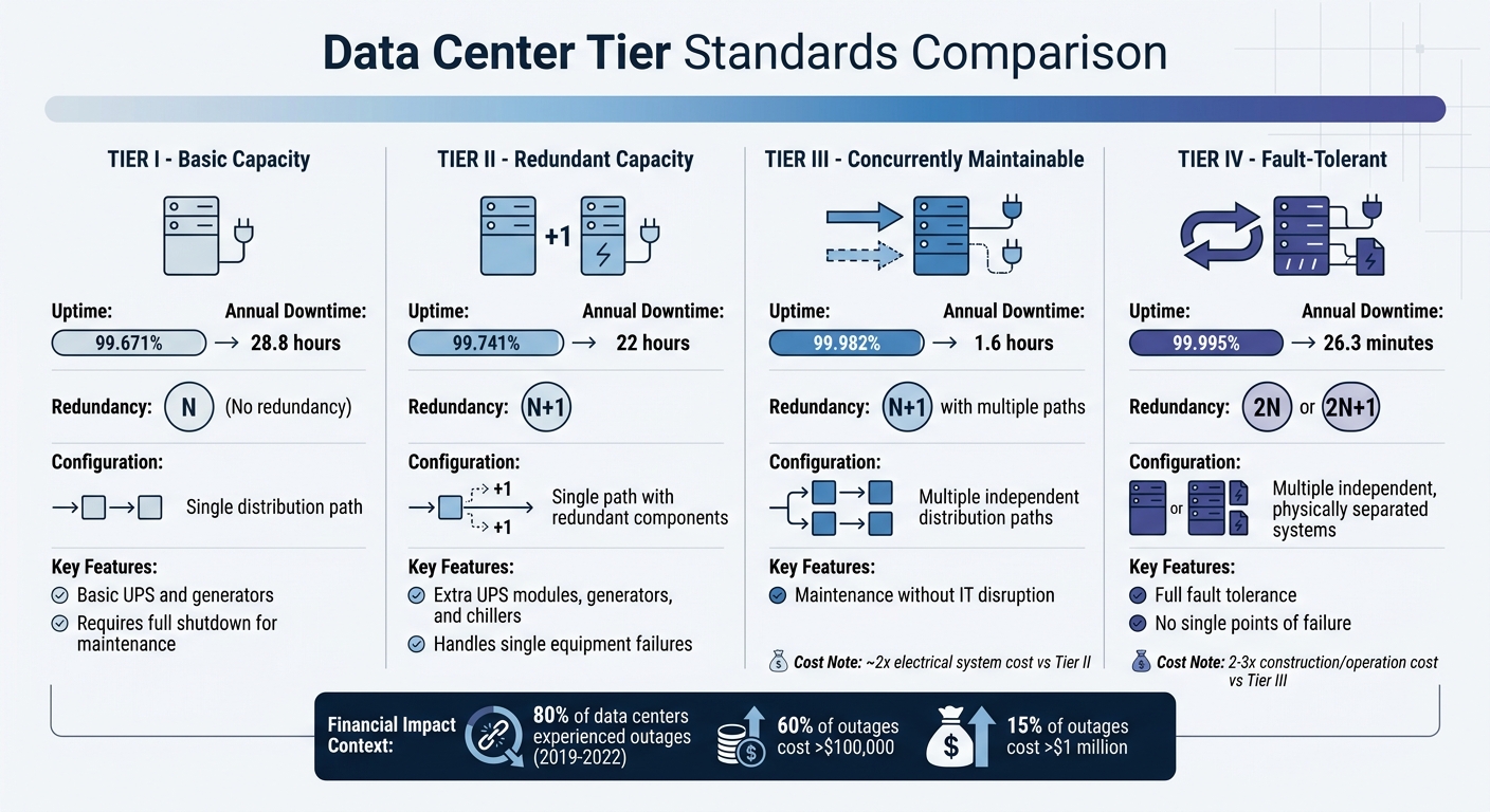
Data Center Tier Standards: Uptime, Downtime, and Redundancy Comparison
What Are Uptime Tier Standards?
The Uptime Institute Tier Classification System is a globally recognized framework for assessing data center infrastructure based on factors like redundancy, maintainability, and fault tolerance. This system categorizes facilities into four tiers, with each level building on the requirements of the previous one by adding stricter standards.
- Tier I (Basic Capacity): Relies on a single distribution path (N configuration) with no redundancy. These centers include basic UPS systems and generators but must shut down entirely for most maintenance tasks.
- Tier II (Redundant Capacity): Maintains a single distribution path but incorporates N+1 redundancy, such as extra UPS modules, generators, and chillers, to handle individual equipment failures.
- Tier III (Concurrently Maintainable): Features multiple independent distribution paths (one active, one passive) with N+1 redundancy. This setup allows maintenance work on components without disrupting IT operations.
- Tier IV (Fault-Tolerant): Represents the top standard, requiring multiple independent, physically separated systems with 2N or 2N+1 redundancy. As the Uptime Institute explains:
Tier Certification means that the infrastructure has no weak areas, and the data center has worldwide accountability for excellence.
These tier classifications serve as the foundation for understanding redundancy and uptime expectations at each level.
Redundancy Requirements for Each Tier
Each tier offers a different level of uptime and redundancy. Here’s a breakdown of the availability percentages and annual downtime for each:
- Tier I: 99.671% uptime, equating to 28.8 hours of downtime annually.
- Tier II: 99.741% uptime, or 22 hours of downtime each year.
- Tier III: 99.982% uptime, limiting downtime to just 1.6 hours annually.
- Tier IV: 99.995% uptime, reducing downtime to only 26.3 minutes per year.
The cost of achieving higher tiers increases significantly. For example, moving from Tier II to Tier III nearly doubles the cost of the electrical distribution system due to the addition of redundant switchgear, UPS modules, and wiring. Tier IV facilities are even more expensive, often costing two to three times more to construct and operate than Tier III facilities. However, for mission-critical applications - like high-frequency trading or national security systems - the fault tolerance of Tier IV justifies the added expense. This is especially relevant when considering that 60% of data center outages result in losses exceeding $100,000, and 15% surpass $1 million.
These tier standards provide a roadmap for designing data centers capable of delivering continuous operations, even in the face of potential failures.
Redundancy Configurations Explained
This section builds on tier standards to explain how various redundancy configurations ensure uninterrupted operations.
Types of Redundancy Configurations
At its core, N represents the minimum number of components (like UPS units or generators) needed to handle the full IT load. While this setup is straightforward, it offers no backup - any failure or maintenance leads to downtime.
N+1 steps up by adding one extra component to the required minimum. For instance, if three UPS modules are needed, an N+1 setup includes a fourth as a backup. This approach allows for maintenance or a single component failure without disrupting operations. However, it doesn’t cover the power distribution path itself.
With 2N, the power system is duplicated, creating independent A and B feeds, each capable of handling the entire load on its own. This design ensures that one path can be taken offline for maintenance without affecting operations. Typically, these systems operate at 40–50% capacity to allow room for failover.
2N+1 takes redundancy a step further by mirroring the entire system and adding a spare component. This setup maintains redundancy even if one component fails while another is under maintenance. It’s often used in mission-critical environments like healthcare or financial trading, where fault tolerance is paramount.
A less common option, 3N/2, uses load management to distribute capacity across smaller units. This method reduces idle equipment while still offering redundancy, making it a cost-efficient alternative to full 2N duplication.
Comparing Redundancy Configurations
When evaluating these configurations, fault tolerance, cost, and operational impact are key factors.
Upgrading redundancy often comes with a higher price tag. For example, moving from Tier II to Tier III can double the cost of an electrical distribution system. However, with 43% of data center outages linked to UPS failures and 60% of outages costing over $100,000, the investment in higher redundancy can be well worth it for critical operations.
| Configuration | Fault Tolerance | Capital Cost | Maintenance Impact | Typical Uptime |
|---|---|---|---|---|
| N | None | Lowest | Requires full shutdown | 99.671% (28.8 hrs/year) |
| N+1 | Component-level only | Low-Mid | Allows component maintenance | 99.741% (22 hrs/year) |
| 2N | Path-level (System) | High | Concurrent maintainability | 99.982% (1.6 hrs/year) |
| 2N+1 | Full fault tolerance | Very High | Maintenance + failure protection | 99.995% (26.3 min/year) |
As highlighted by Lawrence Berkeley National Laboratory:
Idle redundancy represents one of the largest controllable efficiency losses in enterprise data centers.
This inefficiency is particularly evident in 2N systems, where transformers and UPS units often run underutilized. However, for organizations where even 26.3 minutes of downtime annually is unacceptable, the added protection of higher redundancy is a worthwhile trade-off.
Each configuration is designed to meet the rigorous demands of tier standards, ensuring smooth and reliable data center operations.
Components of Redundant Power Systems
To ensure data center resilience, it's important to understand the critical hardware components that make redundancy strategies work. Each part of the power chain contributes to maintaining uninterrupted operations.
Utility Feeds and Switchgear
The first safeguard lies in the building’s connection to the electrical grid. Dual utility feeders, sourced from independent substations or transformers, connect to an Automatic Transfer Switch (ATS). This setup ensures that if one utility source fails, the system automatically switches to the backup feed. Medium-voltage switchgear, typically operating between 12 kV and 15 kV, distributes power to unit substations using redundant configurations like ring-bus or looped topologies. These designs allow maintenance teams to isolate specific cables without disrupting the power supply. This robust base supports the essential roles of UPS systems and generators.
UPS Systems and Backup Generators
Double-conversion (online) UPS systems are key for mission-critical loads, offering zero transfer time by continuously converting AC to DC and back to AC.
Generators extend uptime beyond the limits of battery capacity. They must reach their rated voltage and frequency within 10 seconds. Many facilities now favor natural gas generators due to their lower emissions and virtually unlimited fuel supply through utility connections. When sizing generators, traditional UPS systems require units oversized by 2.5 to 3.0 times the UPS rating to manage harmonic distortion. However, modern UPS systems with Active Power Factor Correction (PFC) reduce this requirement to just 1.3 times the UPS rating. Additionally, the electrical system must handle both the IT load and the peak battery charging load - up to 20% of the UPS rating - when recovering from a deep discharge.
Power Distribution Units and Server Power Supplies
After power is converted and backed up, the distribution stage ensures continuity to the servers. Power Distribution Units (PDUs) deliver electricity directly to server racks, forming the final link in the chain. In a 2N configuration, each server receives power from two independent PDUs - one connected to the A-feed and the other to the B-feed. This ensures that even if one path fails, power still reaches the hardware. Dual-corded server power supplies draw power from both PDUs simultaneously, reinforcing the redundancy established earlier in the chain.
"A single UPS module - even one with internal redundant modules - represents a single point of failure at the distribution level. True redundancy requires separate UPS systems on isolated electrical paths feeding separate PDUs at the rack."
- Electrical Trade Network
The demand for robust redundancy has never been greater. Advanced AI GPU clusters now require between 50 kW and 132 kW per rack. A single PDU failure could disrupt a significant volume of data processing, making component-level redundancy at the PDU stage absolutely critical.
Designing and Implementing Power Redundancy
Eliminating Single Points of Failure
To design a reliable power system, start by identifying your reliability target (Tier I–IV), as this will guide decisions from utility feeds to rack-level distribution. For instance, a Tier III facility must support maintenance activities without disrupting the IT load. On the other hand, Tier IV facilities require fault tolerance, ensuring operations continue even if a single failure occurs.
A key principle is to create completely independent A and B power paths with no shared components. This means your A-side and B-side one-line diagrams should avoid any overlapping transformers, switchgear, or other potential weak points. Dual utility feeds from separate substations or transformers are essential, combined with Automatic Transfer Switches (ATS) to seamlessly reroute power during a failure.
When sizing transformers and generators, ensure they can handle the full critical load with an additional 20–25% margin, plus up to 20% more for battery charging needs. Modern UPS systems with Active Power Factor Correction can significantly reduce generator sizing requirements. Instead of the traditional 2.5–3.0 times multiplier, you may only need 1.3 times the UPS rating, which can save between $500,000 and $800,000 for a 500 kW system.
"The true test of redundancy is not normal operation but the ability to sustain service while components are intentionally removed."
- Howard Williams, Associate Editor, Electricity Forum
By following these design principles, you’ll establish a redundancy framework capable of maintaining uninterrupted operations even under stress.
Sourcing Quality Equipment
Once your design is finalized, focus on sourcing components that meet the required standards for performance and reliability. For example, transformers should account for harmonic derating with a factor of 0.85–0.90 or a K-factor of K-13/K-20 to handle non-linear IT loads. Generators must comply with NFPA 110 standards, achieving rated voltage and frequency within 10 seconds of a utility failure.
Look for UPS units featuring Silicon Carbide (SiC) inverters, as these can deliver 97% efficiency even at the partial load levels common in redundant 2N architectures.
For sourcing, platforms like Electrical Trader offer a range of new and used equipment, including transformers, generators, PDUs, and switchgear from trusted brands. Using a centralized marketplace allows you to compare specs, confirm compatibility with your redundancy model, and secure equipment that meets your operational needs. Before deployment, conduct Factory Acceptance Testing (FAT) and Integrated Systems Testing (IST) to simulate potential failures and ensure smooth load transfers. This step is essential to ensuring your design delivers on its promise of continuous operations.
Conclusion
Power redundancy forms the core of data center reliability. Without it, a single failure - whether it’s a transformer, UPS, or utility feed - can lead to widespread shutdowns, impacting thousands of interconnected systems. Research consistently shows that data center outages often result in severe financial losses and operational chaos. To tackle these risks, a well-thought-out redundancy strategy is essential, as detailed in this guide.
Every component in the power system must be designed to withstand failure. A strong redundancy plan removes single points of failure at each level, allowing for maintenance without disrupting service and shielding against unexpected issues. For today’s high-density racks consuming 20–40 kW or more, the impact of a single power failure is immense, making it critical to implement dependable redundant systems.
Designing a resilient system requires precision and discipline. Key steps include defining your target Uptime Tier, establishing fully independent A and B power paths, sizing transformers and generators with sufficient capacity, and ensuring path independence through rigorous integrated systems testing. As Howard Williams from the Electricity Forum highlights:
The true test of redundancy is not normal operation but the ability to sustain service while components are intentionally removed.
Beyond design, sourcing high-quality equipment is vital for maintaining system reliability. Resources like Electrical Trader offer access to transformers, generators, UPS systems, and switchgear that meet the demanding requirements of mission-critical environments.
FAQs
How do I choose between N+1, 2N, and 2N+1?
Choosing between N+1, 2N, and 2N+1 depends on your specific needs for reliability, budget constraints, and how you prioritize maintenance:
- N+1: Includes one backup component, offering basic redundancy. This strikes a balance between cost and reliability, making it a practical choice for many setups.
- 2N: Completely duplicates critical systems, ensuring maximum uptime. It's best for operations where downtime is simply not an option.
- 2N+1: Takes 2N a step further by adding an additional layer of redundancy. This approach provides the highest level of reliability and simplifies maintenance, though it comes with a higher price tag.
What are the most common power single points of failure?
In data centers, some of the most frequent single points of failure (SPOFs) involve critical components like utility feeds, transformers, switchgear, uninterruptible power supply (UPS) systems, and branch circuits. These elements are essential for distributing power throughout the facility, and any failure can lead to outages if backup systems aren't in place.
To reduce these risks, many data centers adopt redundancy strategies such as 2N or 2N+1 configurations. These setups ensure that backup systems can take over immediately in the event of a failure, helping to maintain uninterrupted operations and minimize downtime.
What testing proves a redundant power design actually works?
Testing a redundant power design focuses on ensuring the system can handle failures smoothly and switch to backup systems without interruptions. One common approach is failover testing, where a primary system is deliberately taken offline to confirm the backup system activates seamlessly.
For instance, a 2N redundancy setup duplicates all critical components. If one component fails, the backup immediately takes over, maintaining consistent performance and reducing downtime to an absolute minimum. This approach is crucial for systems where reliability is non-negotiable.


