Color Code Standards for Backup Systems
One wrong wire color in a backup power system can turn a shutdown into a live hazard. If you work with generators, ATSs, UPS units, or battery-backed circuits, the basic rule is simple: in the U.S., neutral is white or gray, ground is green or bare, and phase colors must stay consistent and be clearly labeled.
Here’s the short version:
- NEC/NFPA 70 sets the base rules for building wiring
-
NFPA 79 adds cabinet control-wire colors like:
- Red for AC control
- Blue for DC control
- Orange for circuits still live with the disconnect open
-
IEC 60445 may show up on imported gear, with:
- Brown/black/gray for line
- Blue for neutral
- Green-yellow for earth
- In multi-source sites, color alone is not enough
- You also need labels, raceway markings, one-lines, and as-builts
- Emergency and UPS systems need extra source marking because backfeed can leave parts live even after shutoff
A few field rules matter most:
- Keep phase ID the same from generator to ATS to panel
- Mark every emergency enclosure “Emergency System”
- Label UPS outputs with backfeed warnings
- Re-identify imported or mismatched conductors at each termination, splice, and access point
- In buildings with more than one voltage system, use one fixed identification method per system
The big point: I’d treat wire color as the first clue, and labels as the final proof. That’s what helps people trace power sources, avoid cross-connections, and pass inspection with fewer mistakes.
Electrical Wire Color Coding Used By Electricians
sbb-itb-501186b
Standards That Govern Backup Power Cable Identification
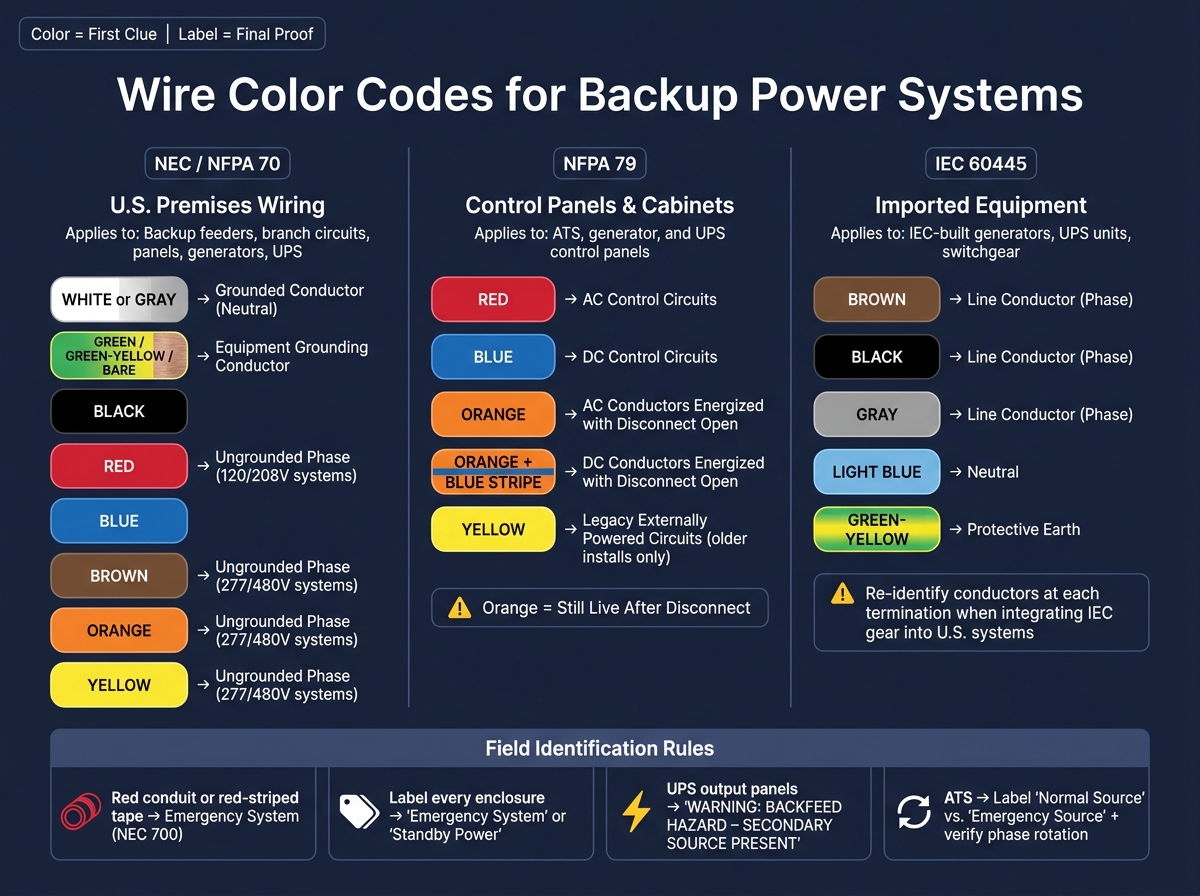
Wire Color Codes for Backup Power Systems: NEC, NFPA 79 & IEC 60445 Guide
Three standards guide backup cable identification: NEC/NFPA 70, NFPA 79, and IEC 60445. Each one covers a different part of the system. Knowing where each standard applies makes design, purchasing, and field work a lot easier.
| Standard | Scope | Key Color Rules | Where It Applies |
|---|---|---|---|
| NEC / NFPA 70 | Premises wiring: feeders, branch circuits, panels, generators, UPS | White or gray for grounded conductors; green, green/yellow, or bare for equipment grounding conductors; other colors for ungrounded conductors | Backup feeders and branch circuits |
| NFPA 79 | Industrial machinery and control panels, including generator and UPS controls | Red for AC control circuits; blue for DC control circuits; orange or yellow for circuits that remain energized with the main disconnect open | ATS, generator, and UPS control panels |
| IEC 60445 | IEC-designed equipment and imported gear | Brown, black, and gray for line conductors; blue for neutral; green-yellow for protective earth | Imported backup equipment |
NEC and NFPA 70 Rules for Grounded, Grounding, and Ungrounded Conductors
For U.S. backup installations, NEC/NFPA 70 sets the main conductor rules. Grounded conductors, or neutrals, must be white or gray. Smaller conductors must be identified continuously, while larger conductors can be marked at their terminations.
Equipment grounding conductors must be green, green/yellow, or bare. Ungrounded conductors can use other colors, but each phase needs to stay identified the same way at every termination. That consistency matters. If Phase A is one color at the generator and a different one at the ATS, things can go sideways fast.
NFPA 79 Control Wire Colors for Generator and UPS Controls

Inside control cabinets, NFPA 79 adds tighter color conventions. Red marks AC control circuits. Blue marks DC control circuits. Orange or yellow marks circuits that stay energized when the main disconnect is open.
That last group is a big deal in backup systems. A separate UPS bus or a remote battery-fed control circuit may still be live even after the main disconnect is opened. In plain English: the cabinet can look off, but part of it still has power. Color coding gives technicians a clear warning before they put their hands inside.
IEC 60445 as a Reference for Imported Equipment
Imported equipment may use a different color scheme. Generators, UPS units, and switchgear built to IEC 60445 use brown, black, and gray for line conductors, blue for neutral, and green-yellow for protective earth.
Before making terminations, check the manufacturer's wiring diagram. Then re-identify conductors as needed so they match the project standard. That extra step can prevent mix-ups when IEC-built gear is installed in a U.S. backup system.
Next, apply these standards to the actual conductor colors used in U.S. backup systems.
Core Conductor Colors Used in U.S. Backup Power Installations
If the wire colors from the manufacturer don't line up with the project standard, re-identify each conductor at every termination, splice, and access point. Use permanent marking, such as phase tape or heat-shrink tubing.
In buildings with more than one voltage system, NEC 210.5(C) requires one consistent identification method for each system. The next subsections apply that rule to AC phase colors, grounding conductors, and DC battery circuits.
How Emergency, Standby, and UPS Systems Are Identified in the Field
Conductor color by itself doesn't tell you where power comes from. A black phase conductor might be part of a normal circuit, an emergency circuit, or a UPS-fed circuit. Since phase colors show up across multiple systems, labels in the field and markings on raceways do most of the heavy lifting.
So yes, color can give you a clue. But you still need to confirm the source by marking the system itself.
| System Type | Raceway/Jacket Marking | Required Labels | Separation Requirement |
|---|---|---|---|
| Emergency (NEC 700) | Red conduit or red-striped tape | "Emergency System" on all boxes/enclosures | Must be in separate raceways from all other systems |
| Legally Required Standby (NEC 701) | Project-specific conduit identification | "Standby Power" at transfer switches/panels | Can share raceways with other non-emergency loads |
| UPS-Fed Circuits | Facility-standard marking | "UPS Protected" and "Backfeed Hazard" labels | Often kept separate to prevent accidental cross-connection |
| Generator/ATS Wiring | Standard conduit (labeled at ATS) | "Normal Source" vs. "Emergency Source" at ATS | Consistent phase rotation must be verified and labeled |
Emergency and Legally Required Standby Feeders
NEC 700.10(A) requires every box and enclosure on the emergency system to be permanently marked "Emergency System." In the field, red conduit or red-striped tape helps those feeders stand out fast. Add matching labels at each access point, and the system becomes much easier to trace and inspect.
Legally required standby systems under NEC 701 are marked in a similar way, but there is more room in how the work is done. The separation rules also aren't as strict as they are for emergency systems.
UPS-Fed Branch Circuits and Backfeed Hazards
UPS output circuits can stay energized even after the main utility breaker is opened. That's where people can get caught off guard. A panel may look dead, but it isn't.
Every UPS output panel and disconnect should have a permanent label that reads "WARNING: BACKFEED HAZARD - SECONDARY SOURCE PRESENT." Put the same warning on bypass paths too, since those paths can re-energize a bus that seems de-energized.
Use that same source-labeling approach at transfer equipment and generator interfaces so no one has to guess what is feeding what.
Generator and Transfer Switch Wiring
At the automatic transfer switch (ATS), mark each source plainly as "Normal Source" and "Emergency Source." Also label verified phase rotation at the ATS.
That last part matters more than people sometimes think. If phase rotation isn't checked and marked, equipment downstream can end up with a bad surprise during transfer.
Control Wiring, Labeling, and Procurement for Compliant Installations
After field identification comes control wiring. This is where the color rules get stricter inside cabinets and panels.
Control, Interlock, and Monitoring Circuit Colors
These rules matter most in ATS, generator, and UPS controls. Why? Because a conductor can still be live even after the main disconnect is open.
Red marks AC control circuits.
Blue marks DC control circuits.
Orange marks conductors that stay energized with the main disconnect open.
Orange with a blue stripe marks DC conductors in that same condition.
| Color | Circuit Type | Where It Appears |
|---|---|---|
| Red | AC control power - distinguishes control voltage from main power conductors | Contactor coils, relay circuits, start/stop wiring |
| Blue | DC control power - prevents confusion with AC control in mixed-voltage panels | Battery-backed logic, monitoring circuits, DC common |
| Orange | AC conductors energized with the main disconnect off | UPS-fed controls, externally powered interlocks, ATS logic |
| Orange with Blue Stripe | DC conductors energized with the main disconnect off | DC interlock circuits, battery-backed control boards |
| Yellow | Legacy externally powered circuits | Older installations only |
In practice, project specs and manufacturer wiring diagrams still control the final conductor assignment. So even with a standard color approach, the job only works if the convention stays consistent and is documented across the whole installation.
Those color rules don’t do much good if they live only in someone’s head. They need to show up on the drawings and on the equipment itself.
Labels, Drawings, and As-Built Records That Support Compliance
Color by itself is not enough in a multi-source facility. If a site has multiple voltages, multiple sources, and a UPS bypass path, technicians need a legend that connects the dots. And that legend needs to exist not only in the design set, but also inside each enclosure where someone will be working.
| Documentation Item | What It Should Include |
|---|---|
| Enclosure legend / wire-color key | Defines the panel's wire-color key |
| One-line diagram | Power path, source relationships, transfer points, voltage levels |
| Panel schedule | Circuit destinations, loading, spare capacity, source identification |
| Equipment nameplates | Identifies the equipment in the field |
| As-built records | Final wire colors, device labels, deviations from original submittal |
| Cable and conductor labels | Circuit ID at each termination and pull point - supports troubleshooting and inspection |
As-built records need extra attention on backup power projects. Systems often change during commissioning. A transfer sequence gets adjusted, a bypass path gets added, or a field label gets updated. In backup systems, the record needs to make the live source obvious at every enclosure.
Once the color scheme is nailed down in the documents, procurement has to line up with it.
Sourcing Cables and Equipment That Match Project Color Requirements
Before ordering, confirm the color, voltage rating, and available labeling space against the project’s color scheme. A cable can be electrically correct and still fail submittal review if the insulation color doesn’t comply.
That’s why conductor colors should be checked before the order is placed, not after the material shows up on site. Electrical Trader can help source equipment that matches the required voltage, configuration, and identification scheme.
Conclusion: Key Color Code Rules to Apply on Backup Power Jobs
NEC/NFPA 70 is the starting point for all U.S. backup power wiring, and the other standards build from there. In common U.S. practice, black, red, and blue are used for 120/208 V systems, while brown, orange, and yellow are used for 277/480 V systems.
Inside control cabinets, things get more specific. NFPA 79 adds another layer for control wiring: red for AC control, blue for DC control, and orange for conductors that stay energized when the main disconnect is open.
Imported equipment can throw a wrench in the process. IEC-coded panels may use light blue for neutral and brown, black, or gray for phase conductors, so those panels need to be checked and relabeled before termination. After the wire colors are confirmed, field labeling helps finish the job.
Color by itself isn't enough for compliance. Use durable labels and as-built records to identify emergency feeders, standby circuits, and UPS-backed branches at panels and terminations in multi-source systems.
Use color for first-pass identification, and use labels to keep things clear over time.
FAQs
When is wire color alone not enough?
Wire color by itself isn’t enough to identify wiring or keep a backup power setup safe. The install also has to match the wire’s rating, including its voltage limit and whether it’s made to handle conditions like moisture or direct sunlight.
Safety and code compliance also depend on using the right conduit designations, along with following NEC Articles 700 and 701 and any applicable UL certifications.
How should imported IEC-colored wires be re-identified?
In the United States, imported IEC-colored wires need to be re-identified so they match NEC conductor color rules.
The usual fix is simple: permanently mark the wire ends with tape, heat-shrink tubing, or labels that show the wire’s U.S. function. For example, use white or gray for neutral and green or green-yellow for grounding.
That extra step helps meet code and cuts down on installation mistakes.
What labels are required for UPS and emergency systems?
UPS and emergency power supply systems need a few must-have safety and maintenance labels.
Under UL 1778, manufacturers have to include:
- caution labels for non-isolated battery supplies
- instructions for handling vented batteries
NFPA 70B 2026 also uses color decals to show equipment status at a glance:
- White: serviceable
- Yellow: limited serviceability
- Red: nonserviceable equipment that needs immediate repair or replacement
Emergency system enclosures also have to meet local fire-resistance and safety marking rules.