Article 690 Solar Wiring Explained
Solar wiring has unique challenges that require specific safety standards. Article 690 of the National Electrical Code (NEC) sets the rules for photovoltaic (PV) systems, ensuring safety and reliability. This includes guidelines for wiring, grounding, voltage limits, rapid shutdown, and labeling. Here's what you need to know:
- Why It Matters: Solar arrays generate electricity whenever sunlight is present, even during emergencies. This creates safety risks that traditional electrical systems don't face.
-
Key Rules:
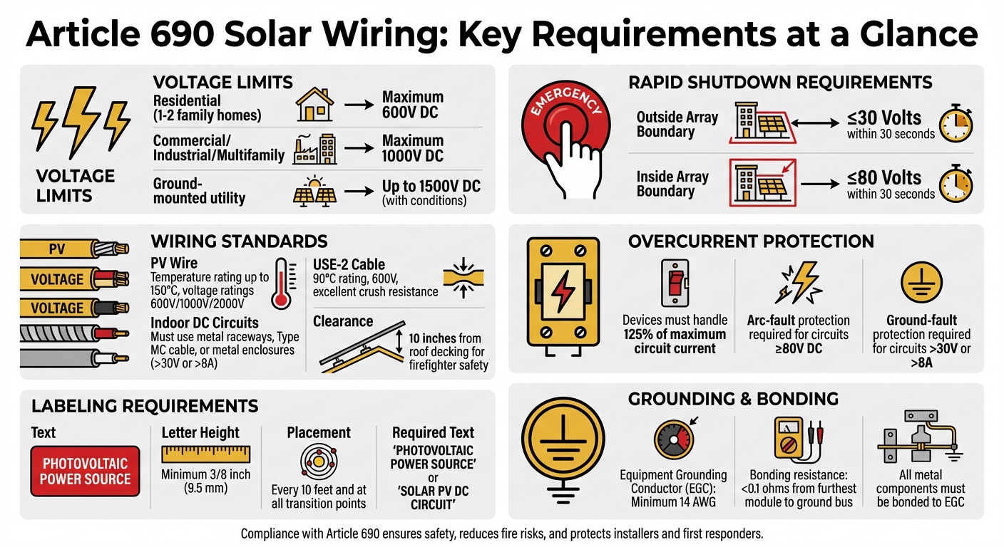
- Voltage Limits: Residential systems are capped at 600V DC; commercial setups can go up to 1000V DC.
- Rapid Shutdown: Systems must reduce voltage to 30V or less within 10 seconds for firefighter safety.
- Wiring Methods: Outdoor PV circuits often use PV wire or USE-2 cable; stricter rules apply indoors.
- Grounding and Bonding: Metal components must be bonded to prevent electrical hazards.
- Overcurrent Protection: Devices must handle 125% of the circuit's maximum current.
- Labeling: Clear, durable labels are mandatory for safety and maintenance.
Understanding these rules is essential for anyone working with solar systems. Proper compliance ensures safety, reduces risks, and aligns with U.S. regulations.
Article 690 Solar Wiring Requirements and Safety Standards Overview
2023 NEC Poetry Reading Article 690 Part 2 Circuit Requirements
Definitions and Scope of Article 690
Getting familiar with the terminology in Article 690 is essential. As Mike Holt puts it, "A key step to avoiding [failure] is to take the time to learn the definitions in 690.2". These terms establish the regulatory framework and clarify how different parts of photovoltaic (PV) systems connect and interact.
Core Terms in Article 690
Article 690 separates PV system circuits into distinct categories, each governed by specific rules. For example:
- PV Source Circuit: This includes the conductors between the solar modules and the DC combiner or inverter terminals - commonly called "strings."
- PV Output Circuit: When source circuits converge, they form the output circuits, which run from the DC combiner to the inverter's DC input terminals.
- Inverter Output Circuit: On the AC side, this circuit carries power from the inverter to the building's electrical system, linking the solar setup to the electrical panel.
These distinctions are critical because they determine the standards for voltage, conductor types, and protective measures.
Modern PV systems often use functional grounding, achieved through electronic connections in the inverter. Mike Holt explains, "Grounding means you make a connection to the earth, and bonding means you make a connection to a low impedance metallic path". Grounding helps manage lightning strikes and voltage surges, while bonding minimizes the risk of hazardous voltages on equipment frames.
What Article 690 Covers
Article 690 applies to all PV systems, including array circuits, inverters, and charge controllers, whether they’re installed in residential, commercial, or specialized environments. It covers grid-tied systems, off-grid setups, and hybrid systems with battery storage, setting the standards for each.
Voltage limits under Article 690 depend on the building type. For one- and two-family homes, the maximum DC circuit voltage is capped at 600 V. In multifamily, commercial, and industrial buildings, this limit increases to 1,000 V. However, large-scale utility PV power plants fall outside Article 690’s scope and are instead regulated by Article 705.
The article addresses more than just panels and inverters. It includes:
- Arc-fault protection: Required for systems operating at 80 Vdc or higher.
- Rapid shutdown systems: Designed to reduce voltage to 30 V or less within 10 seconds.
- Wiring methods: Specific requirements for conductors once they enter a building.
- Conductor identification and grouping: Rules for organizing conductors in shared raceways.
- Accessibility: Ensuring disconnects and equipment are easy to access.
These definitions and standards lay the groundwork for understanding the wiring, grounding, and safety measures outlined in later sections. Up next: a closer look at wiring methods and safety protocols under Article 690.31.
Wiring Methods Under Article 690.31
Article 690.31 lays out the wiring methods designed to ensure the safety of photovoltaic (PV) installations. According to Article 690.31(A), installers can use any wiring method from Chapter 3 of the NEC, along with systems and fittings specifically listed for PV applications. This approach allows for standard electrical installation methods but adds solar-specific requirements. For instance, exposed single-conductor cables are permitted for circuits within the PV array. Ryan Mayfield, Principal at Renewable Energy Associates, highlights this point:
One of the most significant allowances for PV systems is the ability to use exposed single-conductor cables for the circuits within the PV array as called out in 690.31(A).
However, once PV wiring enters a building, there are stricter rules. DC circuits over 30 volts or 8 amperes must be enclosed in metal raceways, Type MC cable, or metal enclosures from the point of entry to the disconnect.
PV Wire and USE-2 Cable Standards
For outdoor PV circuits, two conductor options dominate: Type USE-2 cable and PV wire. While both often use XLPE (cross-linked polyethylene) insulation, they serve different purposes and aren't always interchangeable.
PV wire was specifically developed for solar applications, debuting in the 2008 NEC. It offers temperature ratings up to 150°C and voltage ratings of 600V, 1000V, and 2000V. Its insulation is thicker and undergoes more rigorous flame resistance testing (VW-1). Many solar panels come pre-equipped with PV wire, typically 12 AWG or 10 AWG, attached to their junction boxes.
USE-2 cable, originally designed for underground service entrance applications, is rated for 90°C in both wet and dry conditions and supports up to 600V. It has excellent crush resistance, making it ideal for direct burial in grounded systems. However, for ungrounded (transformerless) systems, PV wire is the only acceptable option for exposed outdoor use. As Ryan Mayfield explains:
In ungrounded systems, only PV wire is allowed for exposed, outdoor locations. If installing an ungrounded inverter, the PV modules used must come with the PV wire attached to them, not USE-2.
Both cable types generally use black insulation for maximum UV resistance and durability in outdoor conditions. To protect the conductors, secure them using stainless steel S-shaped clips or UV-resistant zip ties attached to module frames, which helps prevent abrasion and environmental damage.
Metal-Clad Cables and Raceway Rules
Indoor installations call for stricter measures to enhance safety. Type MC cable for DC circuits must meet NEC 250.118 grounding and bonding standards. When using flexible metal conduit (FMC) smaller than trade size ¾ inch or Type MC cable under 1 inch in diameter across ceilings or floor joists, guard strips must protect the wiring, and these strips must be at least as tall as the cable.
For wiring runs below roof surfaces but outside the PV array perimeter, maintain at least 10 inches of clearance from the roof decking. Mike Holt explains the reason for this requirement:
The 10 in. from the roof decking/sheathing requirement is to prevent accidental contact to energized conductors from saws used by firefighters for roof ventilation during a structure fire.
When conductors share a raceway or junction box, group them by system using cable ties spaced every 6 feet. This practice simplifies maintenance and troubleshooting. Additionally, PV DC circuits must remain separate from non-PV or AC inverter circuits unless physically divided.
In ground-mounted arrays, circuits operating above 30 volts and accessible to unqualified individuals must be installed in raceways or protected by fencing and barriers to restrict access. For outdoor cable trays, single-conductor PV wire is allowed if supported every 12 inches and secured every 4.5 feet.
These detailed wiring methods and protections ensure safety as the system transitions to critical indoor components.
Voltage Limits and Circuit Sizing
Article 690 of the NEC sets specific voltage thresholds based on the location and type of building served by a photovoltaic (PV) system. These limits are designed to safeguard both people and equipment while accommodating a variety of project sizes. The voltage and sizing recommendations build on the wiring practices discussed earlier.
Voltage Limits for Residential and Commercial Systems
For one- and two-family homes, the voltage limit is capped at 600V DC. Meanwhile, commercial, industrial, and multifamily buildings with building-mounted arrays can operate at up to 1000V DC. Ground-mounted utility-scale systems, however, may reach up to 1500V DC if they meet the requirements outlined in NEC 690.31(G). Mike Holt, a consultant for the NEC, explains:
"The maximum PV system DC circuit voltage is the highest voltage between any two conductors of a circuit. It must comply with 690.7,, and. Essentially, this value is limited to 1000V for multifamily, commercial, and industrial buildings, and limited to 600V for one- and two-family residential buildings."
To calculate the maximum system voltage, multiply the total series-connected module Voc by the appropriate temperature correction factor. This factor is determined using ASHRAE's "Extreme Annual Mean Minimum Design Dry Bulb Temperature" data for the system's location. Always use the temperature coefficients provided by the module manufacturer, as per NEC 110.3(B), instead of relying on generic table values. Cold weather can significantly increase module voltage, which might lead to inverter damage or even fire. As Solar Permit Solutions warns:
"Exceeding maximum DC input voltage can cause permanent inverter damage or fire. Many inverters log peak voltage, and manufacturers may void warranties if logs show limit violations."
For larger systems (100 kW or more), calculations may be performed using an engineered, industry-standard method, provided the design is stamped by a licensed professional electrical engineer. The 2023 NEC also includes updated provisions for systems operating between 1000V and 1500V.
2023 NEC Updates for 1000–1500 Vdc Systems
The 2023 NEC introduced Section 690.31(G), which specifically addresses DC circuits operating in the 1000V to 1500V range. These updates prohibit systems exceeding 1000V from being installed on or inside one- and two-family homes or any building with habitable rooms - defined as spaces intended for living, sleeping, eating, or cooking (excluding areas like bathrooms, closets, hallways, and storage spaces).
However, the NEC now allows 1000–1500V equipment to be installed on building exteriors under certain conditions. The equipment must be positioned no more than 10 feet above ground level, and wiring attached to the building's surface cannot extend more than 33 feet from the equipment. Tyson Bittrich from Mayfield Renewables highlights the significance of this change:
"Before the 2023 NEC, placing DC circuits greater than 1000 Vdc on a building's exterior was not allowed. So, while the dimensions (33 ft wide, 10 ft tall) are somewhat limiting for equipment locations, having this option is new to 2023 and could be helpful in specific installation scenarios."
This update is especially useful for compact ground-mount installations where equipment might need to be mounted on the exterior wall of a nearby building. Additionally, the NEC has replaced the term "PV output circuit" with "PV string circuit" in Section 690.7(A) to improve clarity.
Grounding and Bonding Requirements
Article 690 of the NEC makes a clear distinction between grounding - which connects components to the earth to manage voltage surges - and bonding, which links metal parts together to create a reliable, low-impedance path for fault currents.
Grounding Conductors and Connections
Every PV system, whether grounded or ungrounded, requires an Equipment Grounding Conductor (EGC). The EGC provides a fault current path back to the source, ensuring that overcurrent protection devices (OCPDs) function correctly. To determine the correct size for the EGC, refer to NEC Table 250.122 and base it on the OCPD's rating. If no OCPD is installed, size the EGC using the PV system’s maximum circuit current as a reference. The EGC must be a minimum of 14 AWG, and conductors smaller than 6 AWG must be enclosed in raceways or cable armor.
Modern PV systems often use functionally grounded inverters with ungrounded arrays. These inverters establish the ground reference electronically and are capable of detecting faults. While a separate DC grounding electrode, such as a ground rod at the array, is optional under NEC 690.47(B), it must be bonded to the building’s main grounding electrode system to prevent voltage differences between the two grounding points.
NEC expert Mike Holt warns against the unnecessary use of auxiliary electrodes, stating:
"An auxiliary electrode typically serves no useful purpose, and in some cases it may actually cause equipment failures by providing a path for lightning to travel through electronic equipment."
A noteworthy update in the 2023 NEC, Section 690.43(C), now allows EGCs to be run separately from PV conductors within the array. However, once the conductors leave the array, they must share the same raceway or cable for proper installation.
Once grounding is properly addressed, the focus shifts to ensuring secure bonding of all metal components.
Bonding Metal Components
To prevent shock hazards, all exposed metal parts - such as module frames, racking, enclosures, and junction boxes - must be bonded to the EGC. The days of running individual copper wires to each module are largely over. Instead, UL 2703-listed bonding devices, such as clips, washers, and lugs, are now widely used. These devices pierce the anodized coating on aluminum frames, ensuring a reliable electrical connection.
A properly bonded system should have a resistance of less than 0.1 ohms from the furthest module back to the ground bus bar. To achieve this, always torque bonding lugs and clamps according to manufacturer specifications. Loose connections are a leading cause of PV system failures. Additionally, to avoid galvanic corrosion, use compatible metals, such as tin-plated lugs and stainless steel hardware, when connecting copper conductors to aluminum frames.
Wire management is another critical aspect of bonding. Failures in wire management, which occur in 38% of PV projects, can lead to earth faults and pose serious safety risks. Proper bonding ensures the system remains safe and reliable over the long term. For PV circuits exceeding 30 V or 8 A, ground fault protection is mandatory, and ground-fault detectors must activate at currents of 5 amps or less.
sbb-itb-501186b
Overcurrent Protection, Disconnects, and Rapid Shutdown
Article 690 outlines three essential layers of safety for PV systems: overcurrent protection, disconnects, and rapid shutdown. These measures are designed to prevent damage, lower fire risks, and protect anyone working on or near the system during normal use, maintenance, or emergencies.
Overcurrent Protection Devices
Overcurrent protection devices (OCPDs) in PV systems must be rated to handle at least 125% of the maximum circuit current to account for prolonged high output, like around solar noon. If the equipment is listed for operation at 100% of its rating, you can size the OCPD to match 100% of the load.
The method for calculating current depends on system size. For systems under 100 kW, the calculation is based on 125% of the combined short-circuit current ratings of all parallel-connected modules. For systems 100 kW or larger, it’s determined by the highest three-hour current average from simulated local irradiance. Additionally, all OCPDs in PV source (DC) circuits must be listed specifically for use in PV systems.
Beyond protecting against current overload, systems must also allow for safe disconnection under fault conditions. Building-mounted PV systems require two additional safety measures. First, PV DC circuits operating at 80V or higher must include a listed PV arc-fault circuit interrupter (AFCI) to address fire risks. Second, DC circuits exceeding 30V or 8A need Ground-Fault Detector-Interrupter (GFDI) protection to detect and interrupt ground faults.
Disconnect Requirements
Every PV system must include a main disconnect as required by NEC 690.13. This disconnect must isolate all ungrounded DC conductors and be clearly labeled "PV SYSTEM DISCONNECT". It should be capable of simultaneously opening all ungrounded DC conductors and must clearly indicate whether it is in the open (off) or closed (on) position.
The disconnect can consist of up to six switches or circuit breakers housed in a single enclosure or grouped within separate enclosures. NEC 690.15 also requires additional equipment isolating devices for individual components like inverters or charge controllers. A 2023 NEC update now mandates that these isolating devices must be "in sight from" the equipment - visible and within 50 feet - offering more flexibility compared to the previous "within 10 feet" rule.
"The main disconnect, governed by 690.13, must be in a readily accessible location and have an interrupting rating sufficient for the fault current available." - ExpertCE
Rapid Shutdown Requirements
Rapid shutdown is another critical safety measure that works alongside overcurrent protection and disconnects to address voltage risks during emergencies. When triggered, the system must reduce conductor voltage to safe levels within 30 seconds. Conductors outside the array boundary must drop to 30 volts or less, while those inside the array boundary must reduce to 80 volts or less.
| Location | Maximum Voltage | Within |
|---|---|---|
| Outside Array Boundary | ≤ 30 Volts | 30 Seconds |
| Inside Array Boundary | ≤ 80 Volts | 30 Seconds |
Rapid shutdown can be initiated manually through an emergency stop button or automatically in response to events like grid disconnection, an AC breaker trip, or an inverter fault. The 2023 NEC exempts certain open structures, such as carports, solar trellises, and parking shade structures, from rapid shutdown requirements since firefighters rarely conduct rooftop operations on these types of installations. All equipment used for rapid shutdown must be listed or field-labeled for its specific application.
Marking and Labeling Standards
Proper labeling as outlined in Article 690 plays a critical role in identifying voltage levels, circuit types, and shutdown controls. This ensures that electricians, firefighters, and maintenance crews can work safely and efficiently, reducing potential risks. These labeling protocols align closely with the installation practices discussed earlier.
Required Labels for PV Systems
Wiring methods carrying PV power source conductors must include labels reading either "PHOTOVOLTAIC POWER SOURCE" or "SOLAR PV DC CIRCUIT". These labels must use white uppercase letters on a red background, with letters at least 3/8 inch (9.5 mm) tall. Placement is required every 10 feet and at all transition points where wiring passes through walls, partitions, ceilings, or floors.
All disconnects, inverters, and distribution equipment must display the maximum DC system voltage permanently. This ensures workers can select the proper personal protective equipment (PPE) and tools. Todd Fries, Product Category Manager at HellermannTyton, explains:
A single field-applied label indicating the maximum DC voltage must be installed for any PV system with DC circuits. This is required for safety purposes to clearly indicate the maximum voltage to servicing personnel for PPE and tool selection.
For rapid shutdown devices, a reflective label must be installed within 3 feet of the device, using white uppercase letters on a red background. However, the 2020 NEC removed the reflectivity requirement for DC conduit labels, as rapid shutdown technology now improves safety after activation. Additionally, labels at the point of interconnection must indicate the rated AC output current and nominal operating AC voltage. Bipolar systems also require warnings about disconnecting grounded conductors.
Labeling Compliance Guidelines
Beyond content, labels must meet specific durability and environmental standards. They need to remain legible and intact for 20–25 years, withstanding UV exposure, extreme temperatures (ranging from -40°F to 176°F), and moisture.
Before installation, confirm labeling requirements with your local Authority Having Jurisdiction (AHJ). Some areas may require engraved metal plates instead of adhesive labels. If purchasing commercial labeling kits, ensure they use NEC-compliant wording like "WARNING: PHOTOVOLTAIC POWER SOURCE" rather than outdated terms such as "CAUTION SOLAR CIRCUIT". Labels should also adhere to ANSI Z535.4-2011 standards to guarantee visibility and durability over time.
Sourcing Electrical Components for Solar Wiring
When designing a reliable photovoltaic (PV) system, choosing components that meet wiring and safety standards is non-negotiable. Every inverter, disconnect, breaker, and conductor must be explicitly listed for PV applications to comply with Article 690 of the National Electrical Code (NEC).
One crucial factor to consider is temperature ratings. PV modules can heat up significantly under direct sunlight, often reaching temperatures of 70–90°C or even higher. This means conductors need to be rated for wet locations with a minimum temperature rating of 90°C. As Vita Chernikhovska from Nassau National Cable points out:
Because PV modules often reach 70–90°C or higher in direct sun, conductors must be listed for wet locations and have a temperature rating of at least 90°C, though 105°C and 150°C products are also common.
Outdoor components, such as disconnects, junction boxes, and wiring, must be able to withstand UV exposure, moisture, and extreme temperature changes. Additionally, it’s essential to ensure that terminals and lugs are listed for fine-stranded conductors to maintain secure and reliable connections. These factors significantly influence the quality and durability of solar installations, particularly for products sourced through specialized marketplaces.
Electrical Trader Overview
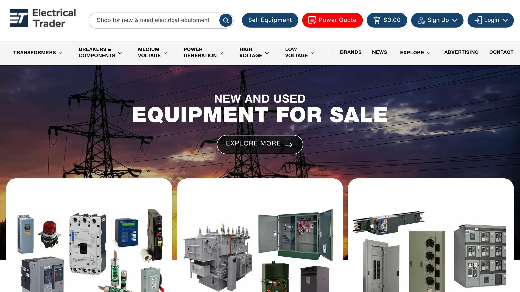
Electrical Trader is an online marketplace designed for buying and selling new and used electrical components. The platform focuses on power distribution equipment, including breakers, transformers, and voltage equipment that meet industrial and commercial standards. This emphasis on quality aligns perfectly with the compliance requirements outlined in Article 690.
PV System Products on Electrical Trader
To meet the stringent requirements of Article 690, Electrical Trader offers a wide range of PV-rated products. These include circuit breakers designed to handle the continuous current demands of solar systems and disconnect switches that enable manual isolation at critical points in the setup. For larger commercial installations, the platform provides three-phase transformers and distribution equipment to support voltage conversion needs.
When sourcing components, always verify that they carry the appropriate certifications. NEC expert Mike Holt underscores this point:
Inverters, PV modules, source-circuit combiners, and charge controllers intended for use in PV power systems must be identified and listed for the application.
Look for UL listings specific to PV systems, such as UL 2703 certifications for grounding and bonding hardware. These standards ensure that the components are suitable for the unique demands of solar installations.
Conclusion
Article 690 isn’t just a rulebook - it’s the backbone of safe and dependable solar installations, designed to protect both people and equipment. Every requirement, from calculating conductor ampacity to ensuring rapid shutdown systems reduce voltage to 30V or less within 10 seconds, is there for a clear safety reason.
Unlike standard electrical systems that can be entirely powered down, solar arrays generate electricity as long as there’s sunlight. This creates unique risks for installers and first responders. That’s why compliance with Article 690 is so critical. Its detailed technical standards help address hazards like overvoltage, arcing, and extreme temperatures. For example, accurate voltage calculations prevent inverter damage in cold weather, while arc-fault protection for circuits over 80V reduces the risk of fires caused by DC arcing. Conductors rated for high temperatures handle the intense heat from modules in direct sunlight. Rapid shutdown systems make it safer for firefighters to work on solar-equipped buildings, and proper equipment grounding ensures electrical continuity and minimizes shock risks.
FAQs
What are the unique safety concerns with solar wiring compared to traditional electrical systems?
Solar wiring comes with unique safety challenges, primarily due to the use of high-voltage direct current (DC), which operates differently from the alternating current (AC) systems used in most traditional setups. In photovoltaic (PV) systems, conductors must be sized to handle at least 125% of the maximum circuit current to maintain safety standards. Overcurrent protection devices must also be rated to match this requirement. The National Electrical Code (NEC) further requires that each PV array has an accessible disconnect switch, clearly labeled as “PV SYSTEM DISCONNECT.” These switches must have lockable or tool-secured covers to prevent accidental access.
Using the correct wiring methods is just as important. DC circuits running above 30 volts need to be protected by guarding, enclosed in Type MC cable, or installed within a raceway. If AC and DC conductors share the same enclosure, they must be physically separated. For outdoor installations, cables must be sunlight- and moisture-resistant to withstand environmental conditions. These measures are critical to minimizing risks such as electrical shocks, fires, and equipment damage - hazards that are less common in standard wiring systems.
For those working on solar installations, Electrical Trader offers a variety of NEC-compliant components, including PV wires, disconnect switches, and overcurrent protection devices. This makes it easier to design and install systems that meet safety and code requirements.
What does Article 690 say about rapid shutdown requirements for solar PV systems?
Under Article 690.12 of the NEC, photovoltaic (PV) systems must include a rapid shutdown mechanism designed to improve safety for firefighters and first responders. This system is crucial because it ensures that the voltage of DC conductors from the array drops to 30 volts or less within 30 seconds of activation.
To meet these requirements, several solutions are available, such as module-level power electronics, listed PV hazard-control devices, or approved mid-circuit interrupters. These options help ensure PV systems adhere to safety standards, providing protection for those who may need to operate near them during emergencies.
What’s the difference between PV wire and USE-2 cable in solar installations?
PV wire and USE-2 cable are both essential in solar installations, but they serve different roles based on their design and intended environment. PV wire is specifically made to endure outdoor conditions. It’s UV-resistant and perfect for wiring solar panels on rooftops or open-air systems. On the other hand, USE-2 cable lacks UV resistance and is designed for applications where it’s protected from sunlight, such as underground installations or inside conduits.
Temperature tolerance is another important distinction. PV wire can handle higher temperatures, with ratings up to 194°F, making it suitable for the heat produced by solar panels. USE-2 cable, however, is rated for up to 140°F, which limits its use in high-heat scenarios. PV wire also offers greater flexibility, making it easier to install in tight or complex setups. In contrast, USE-2 cable is more rigid, commonly used for service entrances or buried feeder lines.
Electrical Trader provides both PV wire and USE-2 cable, ensuring you have the right tools for every aspect of your solar installation.