




Series vs. Parallel Solar Wiring: Key Differences
When deciding how to wire your solar panels, the choice between series and parallel wiring significantly impacts your system's performance, efficiency, and setup requirements. Here's a quick breakdown:
- Series Wiring: Increases voltage while keeping current constant. Ideal for grid-tied systems with high-voltage needs, long cable runs, and MPPT controllers. However, it struggles with shading - one shaded panel reduces the output of the entire string.
- Parallel Wiring: Increases current while maintaining voltage. Best for shaded areas, 12V systems, and PWM controllers. It offers better reliability since each panel operates independently but requires thicker cables and additional components.
Quick Comparison
| Feature | Series Wiring | Parallel Wiring |
|---|---|---|
| Voltage | Adds up (sum of all panels) | Stays constant (same as one panel) |
| Amperage | Constant (same as one panel) | Adds up (sum of all panels) |
| Shade Tolerance | Poor (one panel affects entire string) | Excellent (panels work independently) |
| Cable Requirements | Thinner (10 AWG typical) | Thicker (6-8 AWG typical) |
| Installation Cost | Lower | Higher |
| Best Controller Type | MPPT | PWM |
| Safety Risk | Higher (high-voltage DC) | Lower (safer voltage levels) |
Key Takeaway: Use series wiring for unshaded, high-voltage setups with MPPT controllers. Opt for parallel wiring in shaded areas or 12V systems with PWM controllers. For larger systems, consider a hybrid combination of both methods to balance voltage and current needs.
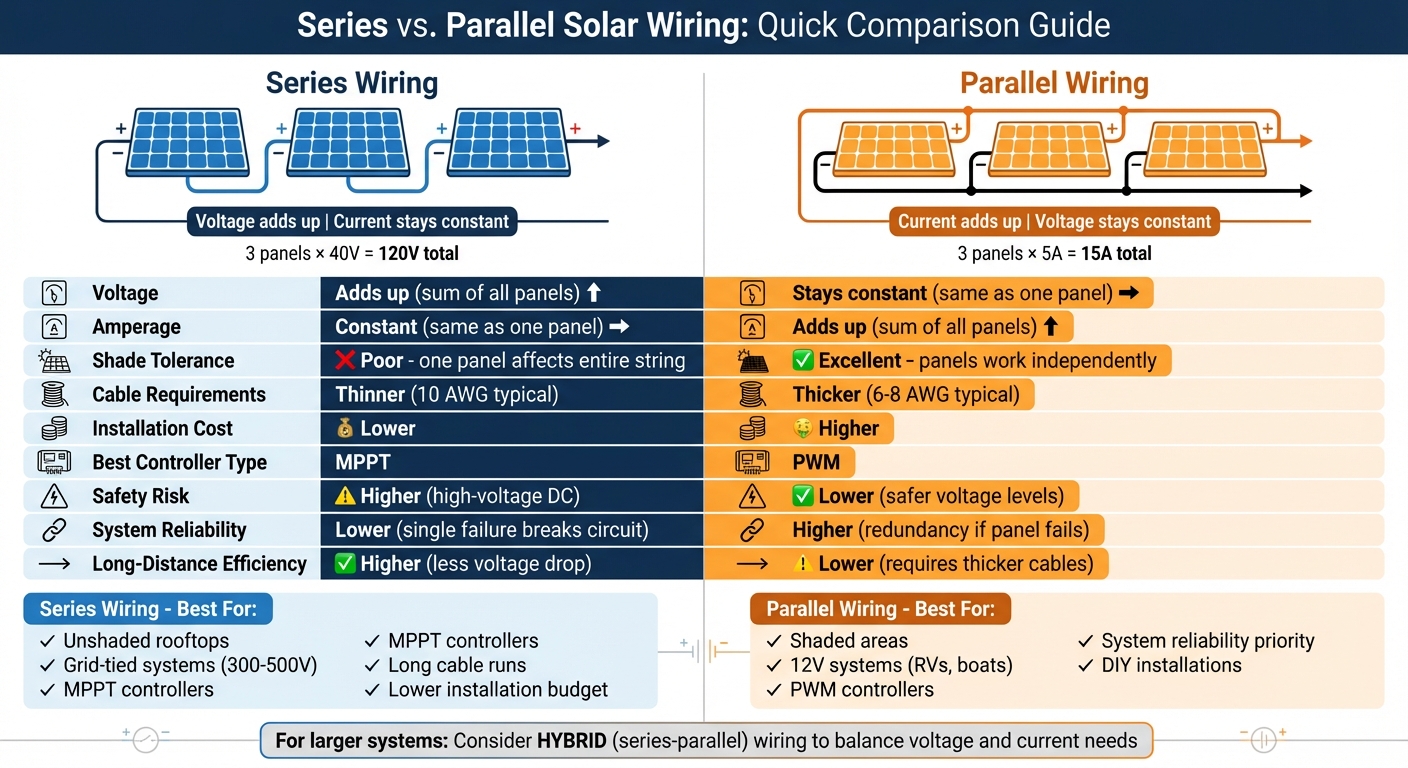
Series vs Parallel Solar Panel Wiring Comparison Chart
Series vs Parallel Solar Panel Wiring Basics - Volts, Amps, Cost & More Explained
sbb-itb-501186b
Series Wiring Explained
Grasping the basics of series wiring is key to ensuring your solar system runs efficiently and is compatible with your setup.
How Series Wiring Works
Series wiring links solar panels in a "daisy chain" by connecting the positive terminal of one panel to the negative terminal of the next. This creates a continuous electrical circuit, often referred to as a "string". Most solar panels come with standard MC4 connectors, making it simple to connect the male connector of one panel to the female connector of the next.
One of the defining features of series wiring is that voltage adds up across all the panels. For example, three 40-volt panels wired in series will produce a total of 120 volts. On the other hand, amperage remains constant, staying at the level of a single panel's output. The final unconnected positive and negative leads at the ends of the string are then connected to your inverter or charge controller. This setup brings several advantages but also comes with a few challenges.
Benefits of Series Wiring
The main benefit of series wiring is its higher voltage output, which makes it perfect for grid-tied systems. Residential string inverters typically need 300–500 volts to function, which can be achieved by wiring 8 to 12 panels in series. Another advantage is better transmission efficiency - voltage travels more efficiently than amperage, reducing energy loss during transmission. This efficiency allows you to use thinner, less expensive cabling, such as 10 or 14 AWG wire.
"Wiring in series is especially useful when you want to use smaller gauge wires. That's because series wiring delivers the same amount of power with less current, and the higher voltage combats voltage drop issues." - GoGreenSolar
Additionally, series wiring simplifies installation. It requires fewer components and less complicated wiring compared to parallel configurations, making the process more cost-effective.
Limitations of Series Wiring
Despite its advantages, series wiring has a notable drawback: sensitivity to shading. Since the current remains consistent throughout the string, the system's overall output is limited by the panel with the lowest performance. If one panel is shaded or damaged, the entire string's output drops to match the weakest panel - similar to how a string of old Christmas lights would fail if one bulb went out.
"The performance of a series configuration is determined by the worst performing panel; an obstruction or poor performance of one panel means they all perform poorly." - Sungold Solar
To avoid these issues, use identical panels and ensure they are installed in areas free from shade. It's also critical to ensure the total voltage of the string doesn't exceed the limits of your inverter or charge controller. Lastly, series wiring typically requires an MPPT (Maximum Power Point Tracking) charge controller to efficiently manage the higher voltage input.
Parallel Wiring Explained
Parallel wiring can be a practical choice for certain solar power setups, offering specific advantages depending on the installation.
How Parallel Wiring Works
In a parallel wiring setup, all the positive terminals of the solar panels are connected together, as are all the negative terminals. This arrangement requires MC4 branch connectors - Y-connectors for two panels, T-connectors for three - and often a combiner box to merge the outputs into a single line feeding the charge controller. The standout feature of parallel wiring is that the total current equals the combined output of all panels, while the voltage remains consistent with the rating of a single panel.
For instance, if you connect two solar panels, each rated at 20 volts and 5 amps, the resulting system will produce 20 volts and 10 amps, totaling 200 watts. This approach works particularly well with PWM charge controllers, which require panel voltage to align closely with the battery bank voltage. These characteristics make parallel wiring a strong option for certain solar installations.
Benefits of Parallel Wiring
A major advantage of parallel wiring is better performance in shaded conditions. Since each panel functions independently, shading or damage to one panel only reduces that panel’s output, leaving the rest of the system unaffected.
"In a parallel setup, shading on one panel has minimal impact on the performance of the others. This makes parallel wiring a better choice for locations with variable shading." - Renogy
Another benefit is system reliability. If one panel fails or becomes disconnected, the remaining panels will continue generating power. This reliability is especially useful in 12-volt systems commonly used in RVs, boats, and motorhomes. Parallel setups also make it easier to expand the system by adding more panels without exceeding the voltage limits of inverters or charge controllers.
Limitations of Parallel Wiring
However, parallel wiring has its drawbacks. Because the total current increases as more panels are added, thicker cables are required to safely handle the higher amperage. For solar panels rated above 50 watts, 10 AWG cables are typically recommended. Additionally, when sizing fuses for a parallel system, it’s wise to use a 1.25 safety factor to account for the increased amperage and reduce the risk of overheating or fire hazards.
Another limitation is the potential for voltage drop over long distances. Parallel systems operate at lower voltages and higher currents, which can lead to efficiency losses if the distance between the solar array and the battery bank is too great. To reduce these losses, it’s best to keep the wiring as short as possible. Additionally, lower voltages can delay battery charging in the morning and shorten charging periods in the evening.
Voltage and Current Comparison
Understanding how voltage and current behave in series and parallel configurations is key to designing an efficient solar system. Here’s the basic idea: series wiring adds voltages while keeping the current steady, whereas parallel wiring increases the current while maintaining a constant voltage.
In a series setup, the total voltage is the sum of the voltages of all panels (V_total = V₁ + V₂ + … + Vₙ), but the current remains the same as that of a single panel (I_total = I₁). On the other hand, in a parallel configuration, the voltage stays at the level of one panel (V_total = V₁), while the total current is the sum of the currents from all panels (I_total = I₁ + I₂ + … + Iₙ). Under identical conditions, the total power (P = V × I) remains unchanged regardless of whether the panels are wired in series or parallel.
Example Comparison Table
Here’s a simple table to make these concepts clearer. We’ll use panels rated at 20V (nominal) and 5A (short-circuit current):
| Configuration | Total Voltage (V) | Total Current (A) | Total Power (W) | Formula Applied |
|---|---|---|---|---|
| Single Panel | 20V | 5A | 100W | N/A |
| Series (2 Panels) | 40V | 5A | 200W | V₁ + V₂ |
| Parallel (2 Panels) | 20V | 10A | 200W | I₁ + I₂ |
| Series (4 Panels) | 80V | 5A | 400W | V₁ + V₂ + V₃ + V₄ |
| Parallel (4 Panels) | 20V | 20A | 400W | I₁ + I₂ + I₃ + I₄ |
When designing systems for actual installations, it’s important to use the open circuit voltage (V_oc) instead of the nominal voltage. This ensures the system doesn’t exceed the maximum voltage rating of the charge controller. Most crystalline solar panels have an open circuit voltage around 40 volts. However, in real-world conditions, panels typically operate at 70% to 80% of their lab-rated output due to factors like temperature, shading, and panel angle.
This analysis of voltage and current provides a foundation for assessing efficiency, shading impacts, and wiring requirements in solar system design.
Series vs. Parallel: Pros and Cons
When deciding between series and parallel wiring for your solar setup, you'll need to weigh factors like voltage needs, shading impact, installation expenses, and overall system reliability. Each approach has its strengths and trade-offs.
Series wiring works well when higher voltage is required, such as for MPPT controllers or long cable runs. However, it has a major drawback: shading. If one panel in the series is shaded, the performance of the entire string drops significantly. On the other hand, parallel wiring offers better shading tolerance and system redundancy, as each panel operates independently. The downside? It demands thicker wires and additional hardware, which can increase costs.
From a cost perspective, the wiring type plays a big role. Series wiring typically uses thinner 10 AWG cables, while parallel setups require thicker cables (6-8 AWG) to handle the higher current. As GoGreenSolar explains:
"Wiring in series delivers the same amount of power with less current, and the higher voltage combats voltage drop issues caused by resistance in the wire."
Shading is another critical consideration. In series wiring, shading on one panel impacts the whole string, while in parallel wiring, shaded panels don’t affect the performance of others, making it a better option for areas with variable sunlight.
Safety is also a factor. Series wiring's high-voltage DC increases the risk of arc faults, whereas parallel wiring operates at lower, safer voltages. However, parallel systems require additional fuses and branch connectors, which adds complexity and cost.
Comparison Table
| Feature | Series Wiring | Parallel Wiring |
|---|---|---|
| Voltage | Additive (sum of all panels) | Constant (same as one panel) |
| Amperage | Constant (same as one panel) | Additive (sum of all panels) |
| Shade Tolerance | Poor (one panel affects entire string) | Excellent (panels operate independently) |
| Cable Requirements | Thinner wire (10 AWG typical) | Thicker wire (6-8 AWG typical) |
| Installation Cost | Lower (fewer cables, simpler hardware) | Higher (branch connectors, combiner boxes) |
| System Reliability | Lower (single failure breaks circuit) | Higher (redundancy if panel fails) |
| Best Controller Type | MPPT (handles high voltage) | PWM (handles high amperage) |
| Long-Distance Efficiency | Higher (less voltage drop) | Lower (requires thicker cables) |
| Safety Risk | Higher (high-voltage DC) | Lower (safer voltage levels) |
Ultimately, the choice between series and parallel wiring depends on your specific solar installation requirements. Each method has its place, and understanding these trade-offs can help you make the best decision for your system.
Efficiency, Shading, and Cable Requirements
The type of wiring you choose for your solar system can significantly impact its efficiency, shading tolerance, and the complexity of cabling. Let’s break down how these factors influence your system's performance and installation.
Series wiring is ideal for long-distance power transmission. The higher voltage in a series setup minimizes transmission losses, even over extended cable runs. For instance, a 100-foot series connection can effectively use 14-gauge wire without a noticeable drop in efficiency.
On the other hand, parallel wiring faces challenges with voltage drops over longer distances due to higher amperage. When the current exceeds 50 amps, much thicker cables, like 4 AWG, are required - even for shorter runs.
Shading tolerance is another key factor to consider. In a series array, partial shading can significantly reduce the current of the entire string. As Battle Born Batteries explains:
"If shade covers a single panel of your series array, it will bring down the whole system's power output".
In contrast, parallel wiring allows each panel to operate independently. This means shading on one panel typically impacts only that panel's output, making it a better choice for areas with inconsistent sunlight.
Performance in low-light conditions also varies. Series wiring tends to perform better during early mornings, late afternoons, or cloudy weather because the combined voltage makes it easier to meet the battery charging threshold. Parallel systems, however, require higher capacity to achieve the same voltage in similar conditions.
Cable requirements further shape installation decisions. Parallel systems, which carry higher amperage, demand thicker wires (usually 4–8 AWG) and additional components like branch connectors or combiner boxes. Series wiring, with its consistent voltage, can use thinner wires throughout the setup, reducing material costs. For installations where partial shading from trees or chimneys is a concern, the extra cost of parallel wiring might be worth it. As Renogy points out:
"parallel wiring is a better choice for locations with variable shading".
Understanding these factors is crucial to designing a solar system that meets your efficiency and installation needs.
When to Use Series Wiring
Series wiring is ideal for high-voltage systems in locations with minimal shading. It's a great fit for grid-tied setups needing 24V or higher inputs and off-grid systems that rely on MPPT charge controllers. One of its standout advantages is its ability to handle long distances between solar panels and charge controllers, making it a smart choice when panels are installed more than 10–15 feet away. The higher voltage helps reduce energy loss over extended cable runs.
Another benefit of series wiring is its performance in low-light conditions. This configuration allows the system to start charging earlier in the morning and continue later into the evening, even on cloudy days. These features make it particularly useful in specific installations.
For instance, series wiring works well in compact setups like RVs, boats, and camper vans. With limited space and fewer panels, this configuration simplifies installation while maximizing efficiency.
To get the most out of series wiring, pair it with an MPPT charge controller. These controllers are designed to accept high-voltage inputs - often up to 100V or 150V - and efficiently convert that power to charge lower-voltage battery banks. Using a PWM controller with a series-wired array, however, would lead to significant power loss, as it reduces the high voltage to match the battery.
When to Use Parallel Wiring
Parallel wiring works best for setups prone to shading or when you're working with 12V battery systems. Unlike series wiring, which focuses on achieving higher voltage, parallel wiring is better at handling shading issues and is perfectly suited for 12V configurations.
In areas with partial shading, parallel wiring ensures that each panel operates independently. This means a shaded panel only affects its own output, leaving the rest of the array unaffected. This independent operation makes the system more reliable, especially for DIY projects, as a single shaded or faulty panel won’t bring down the entire system’s performance.
This approach is particularly useful for small-scale 12V systems commonly found in RVs, boats, trailers, and camper vans. It maintains a 12V output while increasing the current. If you're using a PWM charge controller - which works best with lower voltage inputs - keeping the array voltage close to the battery voltage improves overall efficiency.
"For a system that has the PWM charge controller, it is better to connect all panels in parallel." - Renogy
To handle the increased amperage that comes with parallel wiring, use thicker cables - such as 10 AWG or 8 AWG - to reduce voltage drop, especially if the panels are more than 10 feet away from the charge controller. For smaller setups with 2–3 panels, Y- or T-branch connectors are a practical solution. Larger arrays, however, benefit from using a combiner box with appropriate fuses for safe and efficient operation.
Combining Series and Parallel Wiring
When scaling up a solar system beyond the limits of either series or parallel wiring alone, combining the two can help optimize both voltage and current. This hybrid method - known as series-parallel wiring - starts by grouping panels into series "strings" and then connecting those strings in parallel to a charge controller or inverter.
The key benefit here is balancing the constraints of your equipment. Many MPPT charge controllers have a maximum input voltage of 100V or 150V, while string inverters typically operate within a range of 300V to 500V. Wiring panels in series within each string increases the voltage to meet minimum operating requirements. Then, connecting multiple strings in parallel boosts the total amperage, allowing for higher wattage without exceeding voltage limits.
Take this example: an array of eight 100W panels (22.5V Voc, 5.29A each) can be configured as two parallel strings of four panels. This setup delivers 90V and 10.58A, resulting in a total of 800W. Additionally, this configuration improves shading tolerance. If one string is shaded, the others can continue producing electricity at full capacity.
To ensure the system runs smoothly, follow these best practices:
- Use identical panels within each string, and ensure all strings have an equal number of panels. Mismatched voltages or uneven string lengths can lead to power losses.
- For systems with more than two strings, use a combiner box with fuses for each string to safely consolidate connections before routing them to the charge controller.
- Always calculate the open-circuit voltage (Voc) of your series string and keep it at least 25% below the controller's maximum voltage rating.
This hybrid wiring method offers additional advantages. The series wiring component allows for thinner, more cost-effective wires over long distances, while the parallel wiring increases the system's amperage to handle larger loads. Because it balances voltage and current demands, series-parallel wiring has become a standard choice for large residential, commercial, and hybrid solar systems, especially those integrating battery storage and grid connectivity.
Conclusion
Grasping these wiring methods is key to selecting the right setup for your solar system. Series wiring increases voltage while keeping amperage steady, making it a great choice for MPPT controllers and string inverters. This approach simplifies installation with thinner wiring but has a downside: poor shade tolerance. If one panel is shaded, the entire string's output drops.
On the other hand, parallel wiring boosts amperage while maintaining a constant voltage. It's a solid option for 12V systems, especially in mobile setups or areas with partial shading. Since each panel operates independently, shading one doesn’t drastically affect the others. However, this method requires thicker wiring and additional components.
For larger systems, a series-parallel hybrid offers the best of both worlds. It combines high voltage for efficient inverter performance with enough amperage to handle larger loads. Plus, it offers better shade tolerance compared to pure series wiring.
The right wiring method depends on your specific needs. Opt for series wiring on unshaded rooftops paired with MPPT controllers. Choose parallel wiring for shaded locations or off-grid setups with PWM controllers. For systems with more than four panels, a hybrid configuration might be your best bet. Always ensure your total voltage stays within your equipment's limits, and use appropriately sized fuses to keep your system protected.
FAQs
How does shading impact solar panels wired in series vs. parallel?
Shading impacts solar panels differently depending on whether they’re wired in series or parallel. In a series configuration, all panels share the same current flow. This means that even if just one panel is partially shaded, it lowers the current for the entire string, which can drastically cut down overall power output. On the other hand, parallel wiring allows each panel to function independently. In this setup, a shaded panel only affects its own performance, while the rest of the system continues running at full capacity.
To tackle shading challenges in series systems, designers often incorporate bypass diodes or power optimizers. These devices help maintain voltage by letting current bypass the shaded cells. While parallel systems are less reliant on these components, adding them can still improve system reliability in areas prone to occasional shading. Electrical Trader provides a range of diodes, optimizers, and other equipment to help reduce shading effects and improve solar system efficiency.
What are the cost differences between series and parallel solar wiring?
The cost of wiring a solar system largely hinges on whether you go with series wiring or parallel wiring. Series wiring is often the more budget-friendly option. Why? It operates at a higher voltage, which means you can use thinner wires and fewer components, keeping costs down.
On the other hand, parallel wiring can be pricier. This method requires thicker cables, combiner boxes, branch connectors, and extra hardware to manage the higher current (amperage) levels, driving up the overall expense.
When mapping out your solar system, weigh these factors alongside your system's specific needs to decide on the wiring approach that balances efficiency and cost.
When is a hybrid series-parallel wiring setup the best choice for a solar system?
When you need to boost the voltage of your solar array to meet the minimum requirements of your inverter or MPPT controller - while also keeping the current low to minimize voltage drop and wiring expenses - a hybrid series-parallel wiring setup can be the perfect solution. This configuration is especially helpful in tackling challenges like shading, panels with different ratings, or other factors that could impact energy production.
By blending the strengths of both series and parallel wiring, a hybrid setup offers flexibility and efficiency. It's an excellent choice for solar systems with complex needs or conditions that tend to fluctuate.





