




Checklist for Medium Voltage Equipment Maintenance Offshore
Offshore MV maintenance fails fast when crews skip the basics. If I had to reduce this article to the few points that matter most, I’d say this: lock down permits and isolation first, inspect for salt, moisture, and loose parts second, then use test data and spare-part planning to keep outages from turning into long delays.
Here’s the short version in plain English:
- I’m dealing with medium voltage equipment from 1 kV to 38 kV
- Offshore work is harder because of salt spray, moisture, vibration, weather, and limited access
- Before any task starts, I need:
- a signed PTW
- a logged switching order
- current SLDs, relay settings, labels, and manuals
- confirmed outage, weather, and vessel access
- Before touching equipment, I need to:
- treat it as live until tested
- verify absence of voltage with a rated meter
- isolate backfeeds
- discharge stored energy
- apply temporary grounds rated for fault current
- The main equipment checks cover:
- GIS and switchgear
- breakers
- transformers
- MV cables and terminations
- busbars
- protection relays
- grounding and lightning systems
- turbine MV interfaces and internal cable runs
- The main failure risks offshore are:
- corrosion
- condensation
- insulation breakdown
- loose bolted joints
- cable damage at J-tubes and terminations
- The main tests and monitoring methods include:
- insulation resistance
- contact resistance
- breaker timing
- relay secondary injection
- infrared scans
- partial discharge
- oil testing and DGA
- earth resistance and continuity checks
- A few numbers stand out:
- 34.5 kV MAD: 2.8 feet for unqualified people and 1.8 feet for qualified workers
- transformer core/clamp ground current should stay below 100 mA
- many offshore power agreements target 97% availability
- I also need to watch replacement triggers, especially after:
- major short-circuit duty
- high mechanical operation counts
- flashover marks
- vacuum interrupter shield blackening
- Spare planning matters because some parts, like transformers, can take months or longer to get
The bottom line: this article is about building the same safe routine every time - plan the work, make the equipment dead and grounded, inspect the parts most likely to fail offshore, trend the test results, and line up spares before the next access window closes.
EC&M Asks Video - Medium-Voltage Circuit Breaker Maintenance
sbb-itb-501186b
2. Pre-Maintenance Safety and Work Planning Checklist
After planning, the next step is control. That means permits, isolation, and site checks all need to be cleared before anyone starts work. Do not begin offshore MV work until the checklist is complete.
Permits, Isolation, and Documentation Checks
Start with the paperwork. You need a signed PTW, an issued switching order, and a logged switching record. Operations must issue the switching order or clearance, and every switching action has to be entered in the system switching log.
The crew also needs the full documentation kit on-site. That includes updated single-line diagrams (SLDs), arc-flash labels, relay settings and calibration files, equipment maintenance history, and manufacturer manuals that list torque specs and lubrication types. If any of that is missing or old, fix it before the job starts. The work instructions should also be ready ahead of time, with labor protection, tools, spares, maintenance standards, and hazard analysis clearly laid out.
You also need to confirm the outage with the offshore operations center and line it up with weather and vessel windows before work begins.
| Check Category | Required Items | Reference |
|---|---|---|
| Authorization | PTW signed; switching order issued and logged | OSHA 1910.269 |
| Technical Docs | SLDs, relay settings, equipment history, manufacturer manuals | NB/T 11762-2025 |
| Hazard Analysis | Written work instructions with preventive measures | NB/T 11762-2025 |
| Outage Coordination | Confirmed with offshore operations center; weather and vessel windows aligned |
De-Energization, Grounding, and Site Condition Checks
Once the documents are in order, attention moves to the physical side of the job.
Treat all circuits as energized until they have been de-energized, tested, and tagged. Check for absence of voltage with a properly rated MV instrument, and test that instrument on a known live source first. Then open all breaker and switch contacts, discharge the closing and opening springs, and disconnect any backfeed sources. Apply temporary grounds to all de-energized circuits, and make sure those grounds are rated for the maximum available fault current.
Set arc-flash and shock boundaries before anyone enters the work area. On a 34.5 kV collector system, the Minimum Approach Distance (MAD) is 2.8 feet for unqualified personnel and 1.8 feet for qualified workers. Before opening any compartment, check the arc-flash label on that specific equipment to confirm the PPE level required.
Site conditions matter too. Check wind speed, deck wetness, ambient temperature, and the safety of the access route before starting. Wet or dirty hot sticks lose dielectric strength. Stop hot-stick work in rain.
Once those checks are cleared, move to equipment-specific inspection and testing.
3. Inspection and Testing Checklist by Equipment Type
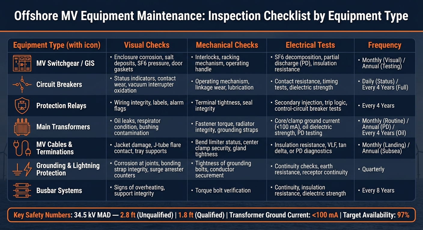
Offshore MV Equipment Maintenance: Inspection Checklist by Equipment Type
Use these checks after isolation and grounding are complete. Think of this section as a field-ready checklist: start with what you can see, move into mechanical checks, then finish with electrical testing. The table pulls the full process into one place.
Switchgear, Breakers, and Protection Controls
Start at the enclosure. Check for corrosion around panel joints, salt deposits on door frames, and any sign of moisture inside the cabinet. Inspect door gaskets for compression and cracking, make sure ventilation paths are open, and replace air filters every 6 months. Also confirm that nameplates, labels, and mechanical status flags match the design documentation.
Then move to the mechanical parts. Operate the racking mechanism, withdrawable units, and shutter systems by hand. They should move smoothly, with no binding or drag. Check all mechanical interlocks and key locks, including Castell locks, to make sure they work as intended. Lubricate hinges, gear trains, and spring-operated parts based on the manufacturer's specs.
For electrical testing, measure insulation resistance across busbars, cables, and control circuits. Run a contact resistance test across closed breaker contacts to spot overheating risk before it turns into a fault. If a breaker has cleared a short circuit, test contact resistance again and verify protection tripping before putting it back in service. You should also test breaker timing, perform secondary injection on protection relays, and confirm auxiliary "a" and "b" contacts. Online partial discharge (PD) monitoring can support condition-based maintenance and cut down on offshore trips.
Transformers, MV Cables, and Terminations
For transformers, do a monthly walk-around. Check the main tank for oil leaks, inspect the respirator, look for contamination on bushing surfaces, and verify that grounding straps are secure. Use a calibrated torque wrench on busbar and terminal fasteners to confirm tightness. Monitor core and clamp ground current during operation; it should stay below 100 mA. Test oil dielectric strength every 4 years, or sooner if moisture ingress is suspected.
For MV cables, inspect the jacket for physical damage, review tray supports, and confirm the bending radius is within limits. At terminations, check gland tightness. On submarine cables, pay close attention to the bend limiter and center clamp at J-tube flare sections. Those parts can detach and stay unnoticed until a fault shows up. Shore landing sections need monthly visual checks, while subsea sections need annual sonar route scanning. For diagnostics, insulation resistance testing is the starting point. If cable history or condition points to more risk, move to VLF, tan delta, or partial discharge testing. At terminations, use infrared scanning under load to catch loose connections before they overheat.
Grounding, Bonding, and Lightning Protection
Offshore, corrosion and loose bonds are common failure points. Inspect grounding conductors for corrosion at connection points, and check that bonding straps on metallic cable parts are intact and tight. Apply conductive grease on handcart grounding tracks to help keep contact resistance low. Measure earth resistance and run continuity checks on all grounding conductors. For lightning protection, inspect surge arrester counters, confirm receptor continuity, and make sure down conductors are undamaged and properly bonded.
Use the table as your field checklist, then log any defects in the maintenance record.
| Equipment Type | Visual Checks | Mechanical Checks | Electrical Tests | Frequency |
|---|---|---|---|---|
| MV Switchgear / GIS | Enclosure corrosion, salt deposits, SF6 pressure, door gaskets | Interlocks, racking mechanism, operating handle condition | SF6 decomposition products, partial discharge (PD), insulation resistance | Monthly (Visual); Annual (Testing) |
| Circuit Breakers | Status indicators, contact wear, no oxidation on vacuum interrupters | Operating mechanism smoothness, linkage wear, lubrication | Contact resistance, timing tests, dielectric strength | Daily (Status); Every 4 years |
| Protection Relays | Wiring integrity, labels, alarm flags | Terminal tightness, seal integrity | Secondary injection, trip logic, control-circuit breaker tests | Every 4 years |
| Main Transformers | Oil leaks, respirator condition, bushing contamination | Fastener torque, radiator integrity, grounding straps | Core/clamp ground current (<100 mA), oil dielectric strength, PD testing | Monthly (Routine); Annual (PD); Every 4 years (Oil) |
| MV Cables & Terminations | Jacket damage, J-tube flare contact, tray supports | Bend limiter status, center clamp security, gland tightness | Insulation resistance, VLF, tan delta, or PD diagnostics | Monthly (Landing); Annual (Subsea) |
| Grounding & Lightning Protection | Corrosion at joints, bonding strap integrity, surge arrester counters | Tightness of grounding bolts, conductor securement | Continuity checks, earth resistance measurement, receptor continuity | Quarterly |
| Busbar Systems | Signs of overheating, support integrity | Torque bolt verification | Continuity, insulation resistance, dielectric strength | Every 8 years |
4. Corrosion Control, Condition Monitoring, and Spare Parts Planning
After you log inspection findings, the focus shifts from finding faults to controlling corrosion and planning spares.
Corrosion Protection and Environmental Controls
Offshore equipment takes a beating from salt spray, humidity, and galvanic corrosion. Over time, those conditions can damage enclosure integrity and insulation.
Start with the enclosure itself. Look for chipped, flaking, peeling, or warped coatings. At joints and metal-to-metal interfaces, check for visible corrosion, since that’s where galvanic attack often starts. Make sure door seam sealing strips are compressed properly and confirm that every fastening screw on enclosure panels is present and tight.
Environmental controls matter just as much. Confirm that dehumidifiers, space heaters, and HVAC systems are operating and set correctly. Breathers and terminal boxes should be clear and working as intended. Pest barriers also need to be intact.
A simple cleaning routine goes a long way here. Clean switchgear enclosures monthly, and wipe down transformer and arrester exteriors to limit salt and dust buildup.
Condition-Based Maintenance and Data Logging
Offshore power purchase agreements typically require 97% availability, which is why condition-based maintenance is becoming more important. The idea is simple: use sensor data to decide when to step in, instead of relying only on calendar-based intervals.
Use trending data to schedule work before failure happens.
Track PD, IR scans, vibration, SF6 decomposition, and oil DGA by asset type and maintenance plan. Log core and clamp ground current and keep it at or below 100 mA. Each record should include the inspection date, technician, equipment ID, measurement, and unit in U.S. format.
Those trend lines also help answer a practical question: which assets need spare parts on hand, and which ones are getting close to early replacement.
Critical Spares and Replacement Decisions
Because offshore access is limited, replacement planning has to start before a part fails.
Long lead times are one of the biggest procurement risks in offshore MV maintenance. Main transformers can take months to procure, and installation may require heavy-lift vessels. That means replacement planning should begin well before a unit shows end-of-life indicators. Major maintenance and heavy-lift replacements should be scheduled during summer months to make the most of usable weather windows.
For replace-versus-repair decisions, lean toward replacement when a device has:
- Cleared a major short circuit
- Exceeded its rated number of mechanical operations
- Shown flashover marks on insulators
Vacuum interrupter shields are another clear warning point. If they’ve lost their metallic sheen or show blackening, that points to vacuum degradation and the unit should be replaced immediately.
| Spare Part Category | Examples | Recommended Stocking | Lead Time Factor |
|---|---|---|---|
| Consumables | SF6 gas, lubricants, cleaning agents, fuses, sealing strips | High stock at the onshore base | Short / Local |
| Critical Spares | Relays, contact kits, surge arresters, MCBs | Medium stock, onshore or shared regional library | Moderate |
| Major Components | Transformers, VCBs, cable segments, J-tubes | Strategic shared library with regional operators | Long (months to years) |
| Specialized Tools | Calibrated torque wrenches, PD detectors, IR cameras | One set per maintenance team | Moderate |
For breakers, transformers, relays, and other replacement MV parts, Electrical Trader can support planned and emergency sourcing.
5. Conclusion: Building a Repeatable Offshore MV Maintenance Program
After planning, inspection, testing, monitoring, and spares review, the program only holds up if every cycle is done the same way. Reliable offshore MV maintenance comes down to repeatability. The same checks, the same tests, and the same records need to happen at every interval.
A checklist only becomes repeatable when each finding is logged against the same asset and its test history. Digital records in a CMMS make that possible. They support accountability, make trend analysis easier, and create an audit trail for compliance. That record also helps teams meet the availability targets common in offshore power purchase agreements, which often require availability above 97%.
Corrosion control and enclosure conditioning aren't side tasks. They're part of the core job. If dehumidifiers, heaters, and enclosure seals aren't working as they should, risk builds fast - even if the electrical test results look fine on paper.
When defects are logged, the next step is simple: check inventory and confirm replacement triggers before the next access window closes. Electrical Trader can help source replacement MV breakers, transformers, relays, and related components.
A disciplined checklist, used the same way every time, documented in full, and reviewed after each cycle, is what separates reactive firefighting from a maintenance program that protects equipment reliability and crew safety offshore.
FAQs
How often should offshore MV equipment be tested?
Testing intervals depend on two things: the component itself and the conditions it works in.
Main transformers usually follow a monthly routine maintenance schedule. Gas-insulated equipment is most often tested once a year for partial discharge, transient ground wave, and SF6 decomposition products.
MV switchgear follows a different rhythm. External inspections are generally done annually. Internal inspections for parts like circuit breakers and cable boxes usually take place every 4 to 8 years.
Age matters too. Newly installed switchgear is often maintained every 3 to 5 years. As that equipment gets older, the interval often shortens to 2 to 3 years.
What offshore conditions cause the most MV failures?
The main drivers are the harsh offshore marine conditions: high salinity, high humidity, and strong atmospheric corrosion. Those conditions speed up mechanical wear, weaken insulation, and eat away at metal parts.
The problem often gets worse during transport and operation at sea. Vibration, wave-driven stress, moisture ingress, and dust buildup can all pile on. In switchgear and transformer systems, that mix often leads to short circuits and insulation breakdowns.
When should MV equipment be repaired or replaced?
Repair or replace medium-voltage equipment based on diagnostic test results, operating history, and the manufacturer’s specs.
If inspections show wear, corrosion, or contamination, take action. Do the same after the equipment clears a short circuit. That check helps confirm the insulating medium and contacts are still fit for service.
For aging assets, use a condition assessment to see whether the equipment is still suitable for service. If insulating oil or other parts can no longer do their job, service or replace them.





