
How to Calibrate Single-Phase Energy Meters
Calibrating single-phase energy meters ensures accurate energy measurement, preventing billing errors. Here's a quick guide:
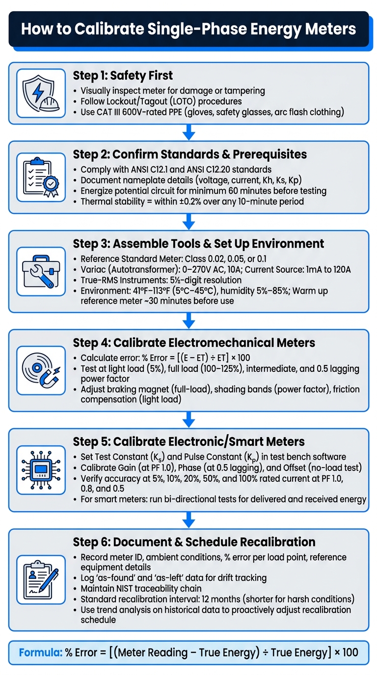
- Safety First: Inspect the meter for damage, follow lockout/tagout (LOTO) procedures, and use insulated protective gear.
- Standards and Requirements: Ensure compliance with ANSI C12.1 and C12.20 standards. Allow meters to stabilize for 60 minutes before testing.
- Tools and Setup: Use a reference standard meter, variac, current source, and True-RMS instruments. Maintain a controlled environment with stable temperature and humidity.
- Electromechanical Meters: Calculate errors using the disk constant (Kh), test under varying load conditions, and adjust mechanical components like braking magnets and shading bands.
- Electronic Meters: Focus on gain, phase, and offset calibration using software registers. Test accuracy across load ranges and power factors.
- Documentation: Record all test parameters, maintain traceability to NIST standards, and schedule regular recalibrations.
Proper calibration ensures reliable performance and compliance with industry standards. Always prioritize safety, precision, and thorough record-keeping.
How to Calibrate Single-Phase Energy Meters: Step-by-Step Guide
Safety, Standards, and Preparation
Safety Precautions Before You Start
Before using any meter or test equipment, start with a thorough visual inspection. Look for signs of physical damage, tampering, or any evidence of a meter bypass. If something appears suspicious, stop immediately and investigate further before proceeding.
When working with live circuits, always follow lockout/tagout (LOTO) procedures. This means de-energizing the circuit, locking it out, and confirming it is no longer live before making any connections. Use insulated personal protective equipment (PPE) like voltage-rated rubber gloves, safety glasses, and arc flash-rated clothing. Ensure that all test leads, probes, and calibrators are rated at least CAT III 600V to handle the transient voltages commonly found in fixed electrical installations.
When working with autotransformers or variacs, always set them to zero before connecting. Gradually increase the voltage instead of applying full voltage instantly.
Applicable Standards and Calibration Prerequisites
Once safety is addressed, confirm that the meter meets the necessary calibration prerequisites.
In the U.S., single-phase meters used for revenue purposes must adhere to ANSI C12.1, which serves as the primary standard for electricity metering, and ANSI C12.20, which covers accuracy classes of 0.2 and 0.5. Before testing, document the meter’s nameplate details, including voltage, current, frequency, and constants like Kh, Ks, or Kp. It's also essential to have a clear understanding of terms like kW, kWh, and power factor, as calibration tests often involve multiple load points and varying power factor conditions.
The formula used to calculate baseline error during calibration is:
% Error = [(Meter Reading − True Energy) ÷ True Energy] × 100
A key step in preparation is allowing the meter’s potential circuit to energize for at least 60 minutes before testing. This gives the potential coil enough time to self-heat and stabilize. A meter is considered thermally stable when its metrological characteristics remain within ±0.2% over any 10-minute period.
Meeting these prerequisites is essential for determining when professional calibration is necessary.
When to Use a Certified Calibration Lab
If field conditions do not meet the required standards, it’s better to rely on a certified calibration lab. While on-site calibration works for routine verifications, certain scenarios call for the precision of an ISO 17025-certified lab or a stationary meter test unit (MTU). For example, type tests, acceptance tests, or official verification tests often require reference standards with accuracy classes of 0.05 to 0.1 - levels that portable field equipment cannot typically achieve.
If the field environment cannot maintain stable conditions - such as consistent temperature, controlled humidity, and minimal electromagnetic interference - a certified lab becomes the best option. Additionally, certified labs ensure traceability to recognized reference standards, which is critical for revenue-grade verification.
Once safety and standards are confirmed, you can move forward with the detailed calibration procedures outlined in the next sections.
sbb-itb-501186b
Calibration Tools, Equipment, and Setup
Tools and Equipment Needed for Calibration
Getting calibration right starts with having the right tools and a stable setup. The cornerstone of this process is a reference standard meter (Class 0.05 or 0.1), which serves as your accuracy benchmark. A good rule to follow: your reference meter should outperform the meter you're testing by at least one accuracy class. For instance, when calibrating a Class 0.5 meter, go with a Class 0.05 reference meter.
Other essential tools include an autotransformer (variac) - capable of handling 0–270V AC at 10A - for smooth voltage adjustments. If you're testing different power factors, such as unity or lagging, a phase-shifting transformer is crucial. For current simulation, an adjustable current source that spans 1mA to 120A will cover everything from light-load to full-load scenarios.
To ensure accurate readings, especially with non-sinusoidal waveforms, you’ll need True-RMS instruments like AC voltmeters, ammeters, and wattmeters. For automating tasks, an optical sampler or scanning head can count disc revolutions on electromechanical meters or LED pulses on digital ones, eliminating manual errors. If you’re going old-school, a simple stopwatch still works for timing disc revolutions during direct-loading tests.
If you're sourcing equipment like autotransformers, reference meters, or test loads, Electrical Trader offers a variety of options, both new and used, suitable for calibration work.
| Equipment | Typical Specification | Purpose |
|---|---|---|
| Reference Standard Meter | Class 0.02, 0.05, or 0.1 | Accuracy benchmark |
| Variac (Autotransformer) | 0–270V AC, 10A | Voltage adjustment |
| Current Source | 1mA to 120A | Load simulation |
| Optical Sampler | Pulse/disc compatible | Automatic revolution/pulse counting |
| Rheostat/Test Load | Variable resistance | Current flow adjustment |
| True-RMS Instruments | 5½-digit resolution | Measures voltage, current, and power factor |
With the tools in hand, the next step is creating a stable and controlled environment for calibration.
Setting Up a Controlled Calibration Environment
Even with the best tools, your results can falter without a controlled environment. Keep the temperature between 41°F and 113°F (5°C to 45°C) and maintain relative humidity levels between 5% and 85% to avoid issues like component drift or degradation. Also, eliminate potential interference - like electromagnetic fields, radio signals, or vibrations - that could throw off your measurements.
Proper wiring and secure connections are just as important. Use a dedicated verification rack or platform to mount the meter securely, ensuring tight, low-resistance connections with pressure gauge holders. Before powering up, double-check that all cables are secure, polarity is correct, and current transformers (CTs) are placed properly. Loose connections or incorrect wiring can lead to inaccurate measurements.
Another critical step is allowing the equipment to warm up. Let the meter’s potential circuit stabilize for at least 60 minutes, while reference standard meters typically require around 30 minutes to reach thermal equilibrium. Skipping this warm-up phase can compromise accuracy. Once stabilized, zero all reference instruments under steady conditions to establish a reliable baseline.
Calibrating Electromechanical Single-Phase Energy Meters
Meter Constants and Error Calculation
Electromechanical meters come with a disk constant (Kh) stamped on their nameplate. This value represents how many watt-hours are recorded per revolution of the induction disc. For instance, if a meter has a Kh of 7.2 Wh/rev, every revolution corresponds to 7.2 watt-hours of energy use.
To find the actual energy (E) recorded by the meter, multiply the number of revolutions by the Kh. Then, calculate the true energy (ET) using a reference wattmeter and a stopwatch with this formula:
ET = (Watts × Time in seconds) ÷ 3,600
Once you have both values, the percentage error can be calculated using:
% Error = [(E − ET) ÷ ET] × 100
A positive percentage indicates the meter is over-recording (running fast), while a negative percentage means it's under-recording (running slow). These calculations should be validated by testing the meter under various load conditions.
Running Calibration Tests at Different Load Points
After determining the initial error, the next step is to test the meter's performance under different load conditions. Before starting measurements, allow the meter to run under load for about 15 minutes to stabilize its temperature.
Here’s a breakdown of common test scenarios:
| Test Condition | Current Level | Power Factor | Measurement Focus |
|---|---|---|---|
| Light Load | 5% of marked current | 1.0 | Friction compensation |
| Full Load | 100%–125% of marked current | 1.0 | Braking magnet accuracy |
| Intermediate Load | Between 5% and 100% | 1.0 | Linearity across the range |
| Lagging Load | Marked current | 0.5 lagging | Shading band (phase) accuracy |
For each load point, time a specific number of disc revolutions (commonly 5 or 10) using a high-precision stopwatch. To minimize timing errors, average multiple readings. Additionally, perform a zero-load (creep) test by applying voltage without load current to confirm the disc remains stationary.
The error measurements obtained will help guide the necessary mechanical adjustments.
Making Mechanical Adjustments
After plotting the error curve for the various load points, there are three key adjustments that can be made to restore meter accuracy:
- Full-Load Correction: Adjust the permanent braking magnet's position. Moving the magnet outward increases braking torque, slowing the disc. Moving it inward decreases the torque. Make small changes and retest after each adjustment.
- Power Factor (Lag) Correction: Adjust the copper shading bands on the shunt magnet's central limb to fine-tune the flux phase. This ensures the flux is 90° out of phase with the applied voltage, which is especially important for accurate readings under inductive loads. Apply this adjustment if errors are evident during lagging-load tests.
- Light-Load Correction: Compensate for internal friction that can affect low-current accuracy, typically around 5% of the marked current. After adjusting, rerun the relevant test to confirm the correction.
Calibration of Single Phase Energy Meter
Calibrating Electronic and Smart Single-Phase Energy Meters
Unlike traditional meters with spinning discs and adjustable magnets, electronic and smart meters rely on software registers, pulse outputs, and precision signal sources for calibration. This process demands careful setup and attention to detail.
Digital Meter Constants and Initial Setup
When calibrating electronic meters, two constants play a crucial role:
- Test Constant (Kₛ): Represents energy units per LED flash or LCD pulse.
- Pulse Constant (Kₚ): Used for external pulse outputs like KYZ contacts.
These constants must be entered accurately into your test bench software to ensure error calculations are correct.
Before calibration, allow your equipment to reach thermal stability. Perform tests in a controlled environment, ideally at 73°F (23°C), as this matches the conditions most test equipment is designed for. Additionally, confirm the meter is connected to its required control power source; skipping this step is a frequent cause of failed verification tests.
Once your equipment is stable and constants are set, you can begin calibrating the gain, phase, and offset settings.
Calibrating Gain, Phase, and Offset
Using the constants as a foundation, calibrate gain, phase, and offset in sequence to address specific measurement errors.
- Gain Calibration: Start by applying a known voltage and current at a power factor of 1.0. Compare the meter's pulse output or register reading to a reference standard that is 6 to 10 times more accurate than the meter being tested. Adjust the gain register until the meter's output aligns with the reference.
- Phase Calibration: This step corrects errors caused by current transformers or sensing circuits. Set your calibrator to simulate a specific phase angle, such as 60° for a 0.5 lagging power factor. Adjust the phase compensation register until the meter's active power reading matches the reference.
- Offset Calibration: Perform a no-load test by applying voltage with no current flow. The meter should display zero energy. If it doesn’t, adjust the offset register to eliminate errors caused by electronic noise or internal leakage.
After any adjustment to voltage, current, or phase, wait at least 10 seconds before proceeding to ensure stable meter pulsing.
Verifying Accuracy Across Load Ranges and Power Factors
Once gain, phase, and offset are properly adjusted, test the meter's accuracy across a range of load points and power factors. A typical sequence includes 5%, 10%, 20%, 50%, and 100% of the rated current, tested at power factors of 1.0, 0.8, and 0.5. This ensures the meter maintains accuracy across its full operating range.
"To help ensure the accuracy of the test, it is recommended that you use a reference device or reference energy standard with a specified accuracy that is 6 to 10 times more accurate than the meter under test." - Schneider Electric
For smart meters used in solar or distributed energy setups, conduct bi-directional tests to verify accuracy for both delivered (grid to load) and received (load to grid) energy. If the meter is installed on circuits with non-linear loads, use a calibrator capable of simulating harmonics to confirm the meter performs reliably under distorted conditions.
Lastly, if your test bench counts LED pulses using an optical sensor, use a light-blocking hood to prevent interference from fluorescent lights or sunlight. Such interference can cause false counts, leading to inaccurate error calculations.
Documentation, Traceability, and Maintenance
Accurate calibration isn't just about the process itself - it’s about meticulously recording every test parameter and environmental condition involved.
Recording and Storing Calibration Data
When calibrating, make sure to document key details like the meter ID, manufacturer, model type, ambient conditions, and test settings. Include the percentage error for each load point, along with information about the reference equipment and its current certification status.
Maintaining an unbroken NIST traceability chain is crucial. As Techmaster Electronics explains:
"Every calibration certificate represents an unbroken link to National Standards."
For digital meters, tracking firmware versions is equally important. Software updates can alter calibration parameters, and version history helps identify otherwise hidden anomalies. Modern tools, such as the GF112V2 handheld calibrator, make this easier by storing up to 20,000 sets of calibration data. These can be exported to PC management software, reducing manual errors while ensuring traceability.
Additionally, always log the "as-found" state of the meter before making any adjustments. Comparing this data with the "as-left" results from previous sessions is the best way to detect drift over time. These comprehensive records not only ensure traceability but also help schedule timely recalibrations, keeping systems accurate and reliable.
Setting Recalibration Intervals
Meter performance depends on two things: thorough documentation and regular maintenance. Good records make it easier to plan maintenance proactively.
For most high-precision calibrators, the standard recalibration interval is 12 months. This timeframe works well for meters in stable environments. But if a meter is exposed to heavy use, frequent transport, or harsh conditions, shorter intervals might be necessary.
The best way to determine recalibration frequency is through trend analysis. By reviewing historical as-found data from multiple calibrations, you can spot patterns of increasing error. If a meter’s accuracy starts creeping toward its specification limits, it’s time to tighten the recalibration schedule.
To catch issues early, consider intermediate cross-checks using a reference standard between formal calibrations. These checks can identify drift before it causes billing errors or compliance problems. As Techmaster Electronics notes:
"Undetected meter drift can skew energy readings and cause massive billing disputes or financial losses."
Don’t forget to consider local regulations. Some regions have legal requirements for recalibration. For instance, Measurement Canada mandates specific "reverification periods" to ensure meters remain legal for trade. Always review the rules in your area before finalizing a recalibration schedule.
Conclusion
The final steps in the calibration process are crucial for ensuring the long-term reliability of single-phase energy meters. After following the safety and equipment setup guidelines, the calibration process should include visually inspecting the meter, allowing for proper thermal stabilization, and verifying accuracy under full load, light load, and varying power factors. Whether you're working with electromechanical or digital meters, the same level of care must be given to inspection, testing, and thorough documentation. Every adjustment made should be tested, and every result carefully recorded.
It's important to remember that accuracy, safety, and documentation are interconnected. Even a perfectly calibrated meter can become a liability if its documentation is incomplete or inaccurate. Maintaining detailed records - such as as-found and as-left data - ensuring NIST traceability, and planning recalibrations based on real performance trends are essential steps in creating a proactive and reliable metering program.
For those in need of high-quality calibration tools and accessories, Electrical Trader is a great resource. They offer a wide range of new and used electrical components, including calibration tools and reference standards, all in one convenient location. Investing in reliable tools not only simplifies the calibration process but also helps ensure both safety and precision. By combining thorough inspection, precise testing, and meticulous documentation, you can establish a strong and dependable calibration program.
FAQs
How do I know if my reference standard is accurate enough?
Your reference standard needs to be 6 to 10 times more accurate than the meter you're testing. Double-check that all measurement tools, such as voltmeters and ammeters, deliver dependable readings. Make sure the standard is traceable to national standards through accredited comparisons. Also, let the equipment warm up according to the manufacturer's instructions to ensure it operates at its best.
What load points should I test to prove revenue-grade accuracy?
Testing for revenue-grade accuracy involves measuring performance across critical load points within the meter's operating range. This typically includes assessments at full load (100% of the rated current), light load (10%), and intermediate levels such as 5%, 20%, and 50%. Additionally, testing at a power factor of 0.5 (lagging) is essential to ensure the meter accurately measures phase angles.
When should I use an ISO 17025 calibration lab instead of field testing?
When you need audit-ready data with complete traceability to SI units and documented measurement uncertainty, it’s crucial to use an ISO 17025-accredited lab. These labs provide independent and verified accuracy, making them essential for regulatory compliance, certifications, or tender requirements.
On the other hand, field checks are a simpler option, typically used for routine comparisons between two meters. While they’re convenient, field testing doesn’t offer the detailed documentation or assurance needed for more formal applications.


