How to Calculate Raceway Fill Step by Step
Calculating raceway fill ensures electrical conduits aren't overcrowded, preventing heat buildup, damage, and code violations. Here’s a quick guide:
-
Understand NEC Rules: Use NEC Chapter 9, Table 1 for fill percentages:
- 1 conductor: 53%
- 2 conductors: 31%
- 3+ conductors: 40%
- Nipples (≤24 inches): 60%.
- Know Your Raceway Type: Different conduits (e.g., EMT, PVC) have varying internal areas. Check NEC Chapter 9, Table 4 for exact dimensions.
- Calculate Conductor Area: Use NEC Chapter 9, Table 5 for insulated conductors. Add up the total area for all wires, including equipment grounding conductors.
- Compare Areas: Ensure the total conductor area is within the allowable fill percentage for your chosen conduit.
- Special Considerations: Follow exceptions like the 60% rule for short nipples or the 20% limit for metal wireways.
Mistakes often occur when using incorrect NEC tables or ignoring insulation differences. Use tools like NEC Annex C or manufacturer data for accuracy.
Quick Tip: Aim for 30–35% fill to simplify wire pulling and allow for future adjustments.
Raceway Fill Explained: Using NEC Informative Annex C & Chapter 9 Tables 4 and 5
sbb-itb-501186b
Key Components of Raceway Fill Calculations
Before diving into calculations, it’s essential to understand the three main elements involved: the type of raceway you're using, the conductors that will go inside it, and the NEC (National Electrical Code) rules that dictate how full the raceway can be.
Types of Raceways
The type of raceway you choose has a big impact on the internal area available for conductors. Even conduits with the same trade size can vary in internal area due to differences in wall thickness. As Mike Holt points out:
"Seemingly small decisions in such things as conductor type or raceway type can have a major effect upon how many raceways you must run and how large they must be."
To give you a practical sense of these differences, here’s a comparison of internal areas for common raceway types at the 1-inch trade size, based on NEC Chapter 9, Table 4:
| Raceway Type | Internal Area (100%) | 40% Fill Area (3+ Wires) | Typical Use |
|---|---|---|---|
| EMT | 0.864 in² | 0.346 in² | Commercial/industrial dry locations |
| IMC | 0.959 in² | 0.384 in² | General purpose |
| RMC | 0.887 in² | 0.355 in² | Heavy-duty physical protection |
| PVC Sch 40 | 0.832 in² | 0.333 in² | Underground or corrosive environments |
| PVC Sch 80 | 0.688 in² | 0.275 in² | Areas subject to physical damage |
Notice how Schedule 80 PVC has almost 17% less internal space than Schedule 40 of the same trade size. This difference often requires upsizing the conduit to meet code requirements. Always consult the specific table for your raceway type - using EMT values for an RMC installation, for instance, could lead to incorrect calculations and potential code violations.
It’s also worth noting that metal wireways follow a separate rule: their conductor fill is limited to a maximum of 20% of their cross-sectional area, unlike standard conduits.
Once you’ve established the dimensions of your raceway, the next step is to evaluate the conductor properties to complete the calculation.
Conductor Types and Cross-Sectional Areas
Accurate raceway dimensions are just one piece of the puzzle - conductor properties, especially insulation type, play a key role in determining how much space is used. Wire gauge alone doesn’t tell the whole story. For example, a #12 AWG THHN conductor has a cross-sectional area of 0.0133 in², but a #12 AWG XHHW conductor takes up 0.0181 in² - about 36% more space for the same wire size. This difference becomes significant when you’re running multiple conductors through a single raceway.
For precise values, refer to NEC Chapter 9, Table 5 for insulated conductors and Table 8 for bare conductors. If you're working with compact aluminum conductors, check Table 5A. Additionally, some insulation types like RHH, RHW, and RHW-2 may have an asterisk in Table 5, indicating a smaller cross-sectional area due to the lack of an outer covering. Be careful not to mix up these values, as it’s a common source of errors.
Finally, don’t forget to include equipment grounding conductors (EGCs) in your fill calculations. Even though they don’t count as current-carrying conductors for ampacity derating, they still occupy physical space inside the raceway. Ignoring them can lead to inaccurate results and potential compliance issues.
How to Calculate Raceway Fill: Step by Step
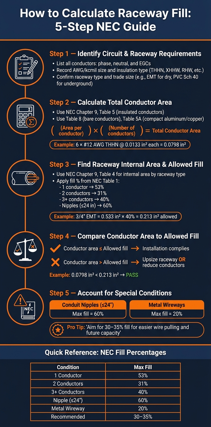
How to Calculate Raceway Fill: 5-Step NEC Guide
Now that you understand raceway types and conductor properties, it's time to dive into the calculation process. Follow these steps to ensure your raceway fill meets NEC requirements.
Step 1: Identify Circuit and Raceway Requirements
Start by gathering all the necessary details about the conductors and raceway, as outlined in the NEC. Make a list of every conductor that will pass through the raceway, including phase conductors, neutral wires, and equipment grounding conductors (EGCs). As NEC Instructor Paul Abernathy advises:
"Get used to taking good notes… you want to write these things down so you're not having to go back and forth."
For each conductor, record its AWG or kcmil size, insulation type (e.g., THHN, XHHW, RHW), and whether it's insulated or bare. Also, confirm the raceway type and trade size based on the environment - such as EMT for dry commercial spaces or PVC Schedule 40 for underground installations. Once you've documented all the conductor details, you're ready to calculate their combined area.
Step 2: Calculate Total Conductor Area
Using NEC Chapter 9 tables, find the cross-sectional area for each conductor. Refer to Table 5 for insulated conductors, Table 8 for bare conductors, and Table 5A for compact aluminum or copper conductors. Multiply the area of each conductor by the number of conductors of that type, then add everything up.
For instance, six #12 AWG THHN conductors have an area of 0.0133 in² each (as per NEC Chapter 9, Table 5). Multiply 0.0133 in² by 6, giving a total conductor area of 0.0798 in². If all conductors are the same type and size, NEC Annex C offers pre-calculated tables to simplify this step.
Once you have the total conductor area, the next step is to determine the available raceway area.
Step 3: Find Raceway Internal Area and Allowed Fill
Look up the internal area of the raceway in NEC Chapter 9, Table 4, based on the raceway material and size. Then, apply the allowable fill percentage from Table 1, which depends on the number of conductors: 53% for one conductor, 31% for two, and 40% for three or more.
For example, a 3/4" EMT raceway with three or more conductors has an internal area of 0.533 in². At a 40% fill rate, the allowed fill area is 0.533 in² × 0.40 = 0.213 in².
Step 4: Compare Conductor Area to Allowed Fill
Now, compare the total conductor area to the allowed fill area. If the conductor area is within the allowable limit, the installation complies. If not, you'll need to either increase the raceway size or reduce the number of conductors.
For example, with a total conductor area of 0.0798 in², the conductors fit well within the 0.213 in² limit for a 3/4" EMT.
Step 5: Account for Special Conditions
Some NEC exceptions and special rules may apply to your installation:
- Conduit nipples (raceways 24 inches or shorter connecting two enclosures) allow a maximum fill of 60%, regardless of conductor count.
- Metal wireways have a stricter fill limit of 20% instead of the usual 40%.
Common Raceway Fill Mistakes and How to Avoid Them
Even seasoned electricians can slip up with raceway fill calculations, leading to failed inspections or even unsafe setups.
Misreading NEC Guidelines
Accurate calculations are only half the battle - you also need to follow NEC guidelines to the letter. A common mistake is defaulting to a 40% fill for all configurations. Instead, you must apply the specific fill percentages listed in NEC Table 1 for different setups. Skipping this step or misinterpreting the guidelines can quickly derail your installation.
Using the Wrong Conductor Area Values
The type of insulation on conductors plays a bigger role than many realize. For insulated conductors, reference NEC Chapter 9, Table 5, and for bare conductors, use Table 8. Pay close attention to the asterisk in Table 5, which highlights reduced conductor areas for insulation types like RHH, RHW, and RHW-2 due to missing outer coverings. This small detail can make or break your calculation. As NEC Instructor Paul Abernathy explains:
"On an exam, if they're giving you those [RHH/RHW], there may be a fact that that slight difference in that covering is a difference between you getting the question right or wrong."
Overlooking Special Conditions
Some specific conditions can trip up even the most diligent electricians:
- The 60% nipple fill rule: This rule applies only to raceways 24 inches or shorter that connect two enclosures. Remember, conduit bodies don't count as enclosures. Misapplying this rule to longer runs violates the code.
- Conduit type matters: The internal area of a conduit varies by type, even if the trade size is the same. For example, a 3/4" PVC Schedule 80 conduit has an internal area of 0.409 in², while a 3/4" EMT conduit offers 0.533 in². Using EMT values for a Schedule 80 installation can lead to overfilling. Always verify conduit types using NEC Chapter 9, Table 4 before finalizing your calculations.
Conclusion and Useful Tools
Summary of Key Steps
To calculate raceway fill effectively, stick to a clear and consistent method. Start by listing all conductors - this includes phase, neutral, and equipment grounding conductors. Then, use the NEC tables to find the area of each conductor and compare the total to the allowable area for the raceway type you're working with.
Remember, the allowable fill percentage depends on how many conductors you’re dealing with: 53% for one conductor, 31% for two, and 40% for three or more. For nipples 24 inches or shorter, you can go up to 60%. However, aiming for a fill of 30–35% is a smarter choice. It makes pulling wires easier and leaves room for future needs.
As NEC expert Mike Holt explains:
"If raceway is too small, you can damage conductors while trying to pull them through. Even if they aren't damaged during the pull, they may overheat inside an undersized raceway."
By following this approach, you can ensure safe and efficient installations.
Recommended Tools and Resources
To make your work smoother, there are several tools and resources you can rely on. If all the conductors are the same size and insulation type, NEC Annex C provides pre-calculated tables that show the maximum wire count - no need for detailed math. For mixed-size runs, online calculators offered by industry leaders can simplify the process.
You might also want to check out Southwire's Re3™ suite, which includes a Cable Pulling Calculator. This tool is especially handy for estimating pulling tension on longer or more complex runs.
For non-standard cables, always refer to manufacturer data sheets since their dimensions may differ from NEC averages. And if you’re looking for raceways, conductors, or other electrical components, Electrical Trader offers a variety of new and used equipment to meet your needs. Accurate calculations and the right tools are key to staying safe and compliant in every project.
FAQs
Do cable assemblies count differently than individual conductors?
When it comes to raceway fill calculations, multiconductor cables are treated differently from individual conductors. According to the National Electrical Code (NEC), a multiconductor cable is considered as a single conductor. This means you use the cable's overall outside diameter to determine its cross-sectional area.
If the cable happens to have an elliptical shape, the calculation requires using the longest diameter of the cable. This ensures accuracy when determining the space it occupies within the raceway.
When do I have to derate ampacity even if fill is OK?
If you have more than three current-carrying conductors in a raceway, you’ll need to reduce their ampacity, even if the conduit fill complies with NEC limits. While conduit fill ensures the wires physically fit without damage, ampacity derating is all about preventing overheating. To adjust conductor ampacity when the number of current-carrying conductors exceeds three, refer to NEC Table 310.15(C)(1). Keep in mind that these two requirements - physical fill and ampacity derating - are entirely separate.
How do bends and pull length affect conduit sizing?
When installing conduits, bends and pull length play a big role in how challenging the installation will be and the potential for damaging conductor insulation. According to the NEC, specific maximum fill percentages are permitted, but these assume no more than two 90-degree bends in the conduit. If there are additional bends, the fill percentage should be reduced by 15% for each extra bend.
For longer runs over 100 feet, it’s smart to aim for a 30–35% fill to avoid issues like jamming. Also, make sure the total bends between pull points don’t go beyond 360 degrees to stay within safe installation limits.