




Cable Fault Locator Tools: TDR, Thumper, PD
If I need the short answer: I use TDR to get the fault area, a thumper to mark the dig spot, and PD testing to check whether the cable has weak insulation.
That’s the whole job in one line. These tools do three different things:
- TDR tells me about how far away the fault is
- Thumper helps me find the exact spot in the field
- PD shows me whether the cable has early insulation damage
A few points matter right away:
- TDR is low-stress and often the first test
- Thumpers work well on high-resistance faults, but they put more stress on the cable
- PD is for condition checks, not fast outage fault location
- For many MV feeders, crews use them in order: TDR → thumper → PD
- TDR pre-location is often around ±1% to 2% of cable length
- After route checks and field work, crews may narrow the search to about 50 to 100 ft, then down to a few feet before digging
- Medium-voltage thumping is often in the 10–30 kV range
Cable Fault Location with Megger Smart Thump and Digiphone
sbb-itb-501186b
Quick Comparison
| Tool | Main job | Best use | Main limit | Cable stress |
|---|---|---|---|---|
| TDR | Pre-locate fault distance | Open-circuit and low-resistance faults | May miss high-resistance faults | Low |
| Thumper | Pinpoint dig location | High-resistance and intermittent faults | Repeated surges can add insulation damage | High |
| PD | Check insulation condition | Repairs, joints, terminations, maintenance | Not built for fast fault distance readout | Medium, depending on test method |
If I’m dealing with an outage, I don’t treat these tools as replacements for each other. I treat them as a sequence. TDR cuts the search area, thumping finds the dig point, and PD helps me judge cable health before or after the repair.
TDR vs. Thumper vs. PD: How Each Tool Works
Each tool works in a different way. And that difference shapes what it can show crews in the field. The big split isn't just what each tool finds. It's how it interacts with the cable.
TDR Units: Distance-to-Fault Pre-Location
TDR units send a low-energy pulse and read reflections to estimate fault distance.
Thumpers: Pinpointing the Fault in the Field
Thumpers apply a high-energy surge that makes the fault easier to hear or see at the surface.
PD Tools: Detecting Insulation Defects Before Failure
PD tools detect discharge activity in insulation defects before they become full failures.
That’s why crews pick tools based on the fault type, the cable’s condition, and how much stress the cable can handle. Those differences shape the speed, cable stress, and accuracy tradeoffs covered in the next section.
Use Cases, Limits, and Tradeoffs for Each Tool
The right tool depends on the type of fault, the condition of the cable, and how much stress the cable can take.
When TDR Is the Fastest, Least Stressful Option
TDR is often the first step when a fault creates a clear reflection. It gives crews a distance estimate without putting much stress on the cable.
For low-resistance faults, TDR can often narrow the search to about ±1% to 2% of cable length. That makes it a strong pre-location tool. The catch? TDR has a hard time when the impedance change is too small. In those cases, the reflection can be weak or easy to miss.
Two things help improve confidence:
- Use the correct velocity-of-propagation setting
- Test from both ends of the cable
When Thumping Pinpoints Faults but Adds Cable Stress
If TDR doesn't give a clear answer - especially with high-resistance or intermittent faults - thumping is usually the next move.
Thumping sends a high-energy surge through the cable to make the fault audible or visible at the surface. That's what makes it so useful for pinpointing. You move from a rough location to the exact spot.
But there's a tradeoff. Every surge adds stress to the insulation. So crews usually follow a simple rule: use the lowest effective voltage and stop as soon as the fault is found.
Thumping can locate the fault with precision, but repeated shots can make existing damage worse. That's why it works best after TDR has already narrowed the faulted section.
When PD Testing Goes Beyond the Immediate Repair
Once the fault is found, the job often shifts from location to cable health.
PD testing helps find developing insulation defects before they turn into failures. That includes voids, contamination, and deterioration in joints and terminations. It's useful after a repair and during planned maintenance when crews want to check the cable's condition, not just fix today's problem.
Still, a clean PD result doesn't mean the cable is perfect. Some defects simply don't produce measurable discharge. So no activity on the test doesn't prove the cable is healthy.
There are limits on the test side too. Off-line PD testing may need test voltages of a few thousand volts to push the cable above PD inception voltage. And, as NIST research has noted, test connections can also create discharges that hide the true defect location.
| Factor | TDR | Thumper | PD Testing |
|---|---|---|---|
| Speed | Fast | Moderate | Slower; requires setup |
| Accuracy | Good pre-location; not exact pinpointing | Precise pinpointing at the fault | Identifies defect zones, not always exact points |
| High-resistance faults | Often poor when the reflection is too weak | Strong; can force the fault to flash over | Not designed for active fault location |
| Effect on cable | Non-destructive | Most stressful; adds insulation stress | Diagnostic; may require elevated test voltage |
| Best for | Pre-location | Pinpointing | Condition assessment and preventive maintenance |
In practice, crews usually follow a clear sequence: pre-locate with TDR, pinpoint with thumping, then check cable condition with PD.
Typical Workflow: Using TDR, Thumper, and PD Together
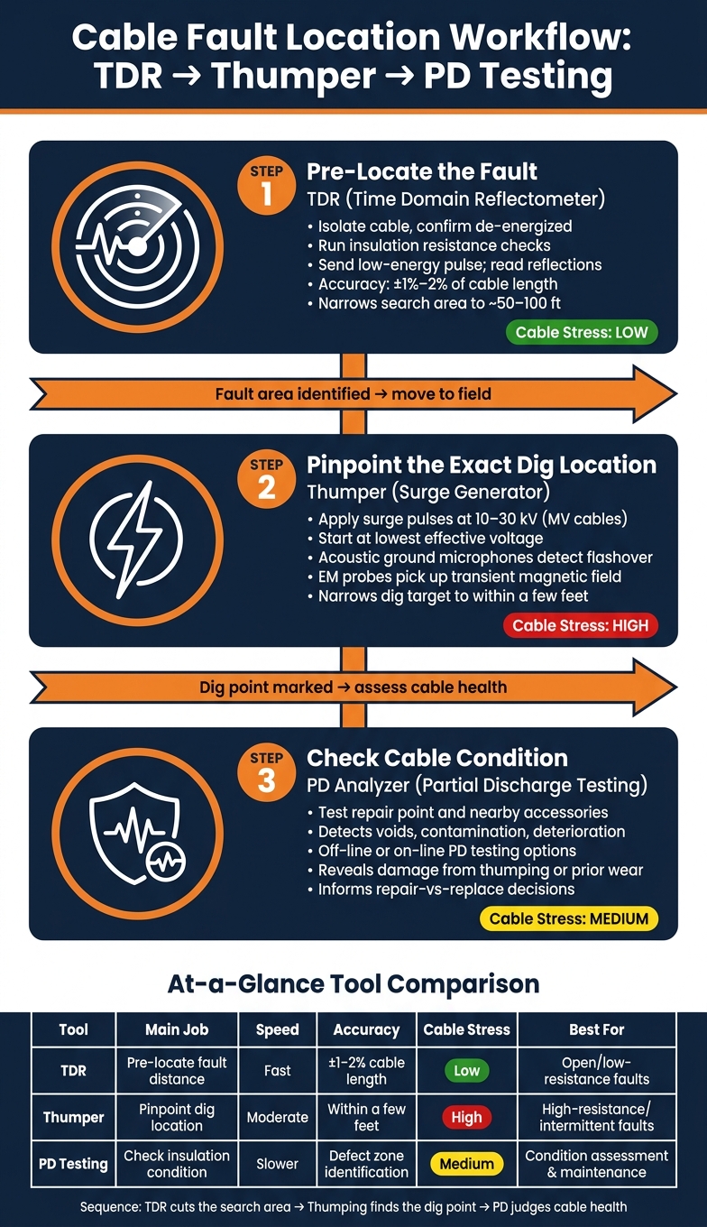
Cable Fault Location Workflow: TDR → Thumper → PD Testing
These tools work best in a set order: TDR first to pre-locate, thumper next to pinpoint, and PD last to check cable condition. In plain terms, crews start by narrowing the search, then find the exact spot, and then look at the cable’s health before or after the repair.
Step 1: Characterize and Pre-Locate the Fault
Crews first isolate the cable, ground it, and confirm it is de-energized. After that, they run insulation resistance checks phase-to-ground and phase-to-phase, along with shield continuity tests, to sort the fault and decide whether TDR or thumper methods make sense.
That first call matters. A low-voltage TDR shot is often enough for low-resistance and open-circuit faults. High-resistance faults are tougher. Those often need arc reflection or impulse current methods, sometimes through an integrated TDR-thumper unit.
Once crews get a distance reading, they compare that electrical distance with route drawings, splice records, and known field landmarks. This step is easy to overlook, but it saves time. Cable length and trench length are not always the same because of slack in manholes, bends, and vertical risers. Done well, this can shrink the search area to about 50 to 100 ft.
Step 2: Pinpoint the Exact Location Before Digging
After crews have a distance estimate, they move into the field. A thumper sends surge pulses - usually in the 10–30 kV range for medium-voltage distribution cables - to force a flashover at the fault. The usual rule is simple: start with the lowest surge voltage that produces flashover, then increase only when needed.
One crew member operates the thumper while others walk the suspected route with acoustic ground microphones and electromagnetic receivers. The acoustic sensors hear the flashover through the soil. The EM probes pick up the transient magnetic field from the surge current. Using both helps a lot when pavement or jobsite noise makes the acoustic signal hard to hear.
Crews mark readings at regular intervals and check the route more than once before calling the spot. That extra pass can mean the difference between a rough guess and digging in the right place. In many cases, the excavation target gets narrowed to within a few feet. Once the dig point is marked, the job shifts from fault location to cable condition checks.
Step 3: Use PD to Check Cable Health Before or After Repair
Fixing the fault is only part of the job. PD testing shows the broader condition of the cable, with close attention to the repair point and nearby accessories. Offline PD testing with a dedicated source, or on-line PD testing at system voltage, can reveal insulation defects that did not show up earlier, including damage that may have been caused by thumping.
If PD is above the acceptance threshold, crews can plan targeted replacement before the next failure hits. And if PD points to degradation across the whole circuit, asset managers have a better basis for a repair-versus-replace call instead of fixing one fault after another. That’s the main role of PD after fault location: it shows cable health and helps crews judge what the repair actually fixed.
Conclusion: Matching the Right Tool to the Job
These tools each do a different job in the fault-finding process. There isn’t one tool that works best for every fault. TDR gives you the fastest, lowest-stress way to pre-locate a fault. Thumpers help crews pinpoint the fault out in the field. PD tools spot insulation defects before a repair happens or after the work is done.
So the practical pick depends on the fault itself and where you are in the repair process. Start with TDR first. Use a thumper when you need to pinpoint the fault. Then use PD testing to check cable condition and help cut down on repeat faults.
If your team is looking for diagnostic gear, Electrical Trader keeps these tools in one place. Electrical Trader offers new and used TDR units, surge generators, PD analyzers, and related electrical test equipment in a single marketplace.
FAQs
When should I use a TDR first?
Use a Time Domain Reflectometer (TDR) first when you need to pinpoint where an insulation defect sits along a cable’s core or sheath.
It’s the main tool for fault location, helping crews identify the trouble spot before they move on to heavier testing or repair work.
Can thumping damage the cable?
Yes. Thumping can damage a cable if the process is rushed, the wrong method is used, or the test itself weakens the insulation.
Thumping uses high-voltage energy to find faults, so careful planning, lockout, and isolation checks matter. If those steps are skipped, the test can make an already bad cable even worse.
What can PD testing find that TDR cannot?
PD testing spots small insulation weak points and early wear that a TDR won't pick up.
A TDR is mainly used to find existing insulation faults or sheath damage. PD testing, on the other hand, detects tiny discharges inside insulation gaps, voids, or cracks. That helps reveal early warning signs like treeing, delamination, or insulation voids before they turn into full insulation breakdown.





