
Top Fault Location Techniques for High Voltage Cables
If you need to find a high-voltage cable fault fast, start with the lowest-stress test and build from there. In most cases, I’d use TDR for low-resistance faults, ARM or ICE for high-resistance faults, Murray or Varley loop tests when a return conductor is available, surge plus acoustic for the exact dig spot, A-Frame for sheath faults, and PD testing to spot weak insulation before failure.
Here’s the short version:
- TDR: best first check for low-resistance faults, opens, and shorts
- ARM: used when the fault is high resistance and TDR alone can’t read it
- ICE: useful for high-resistance, intermittent, and long-run faults
- Murray Loop: low-stress bridge test for shorts, core-to-earth, and some sheath faults
- Varley Loop: bridge test that handles higher-resistance ground and sheath faults
- Surge + Acoustic: used after prelocation to find the exact dig point
- A-Frame: for sheath-to-earth faults only
- PD Diagnostics: for finding insulation weak spots before an outage
A few numbers matter right away:
- Prelocation usually narrows the fault to about 1% to 5% of cable length
- Pinpointing can tighten that to about 0.1%, often sub-meter
- A basic TDR pulse is about 40 V
- Faults under 100 ohms often work with TDR alone
- Surge stress rises with voltage squared (V²), so higher voltage adds much more stress
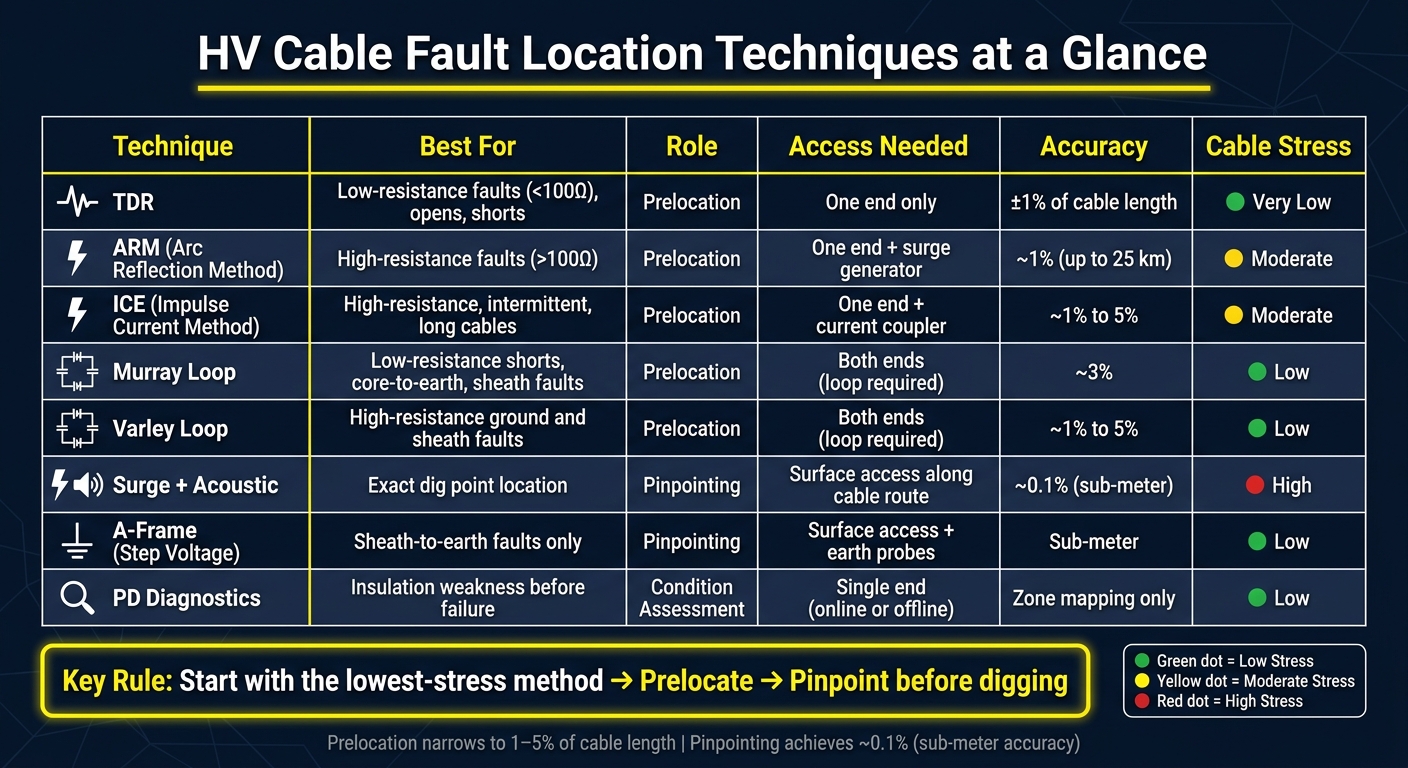
HV Cable Fault Location Techniques: Quick Comparison Guide
Cable Fault Location 202 - Advanced Techniques
sbb-itb-501186b
Quick Comparison
| Technique | Best For | Main Job | Access Needed | Cable Stress |
|---|---|---|---|---|
| TDR | Low-resistance faults, opens, shorts | Prelocation | One end | Very low |
| ARM | High-resistance faults | Prelocation | One end | Moderate |
| ICE | Intermittent, flashover, long cables | Prelocation | One end | Moderate |
| Murray Loop | Low-resistance shorts, core-to-earth, sheath faults | Prelocation | Both ends / loop | Low |
| Varley Loop | High-resistance ground and sheath faults | Prelocation | Both ends / loop | Low |
| Surge + Acoustic | Exact field location | Pinpointing | Route access | High |
| A-Frame | Sheath-to-earth faults | Pinpointing | Route access + soil contact | Low |
| PD Diagnostics | Insulation weakness | Condition testing | Depends on setup | Low |
If I had to reduce the full process to one line, it would be this: identify the fault type, prelocate with the least stressful method, then pinpoint before digging. That approach cuts outage time, limits extra excavation, and helps avoid adding damage during testing.
What Makes a Fault Location Technique Effective?
No single method fits every cable fault. The best choice depends on the fault itself, the cable design, where you can reach the system, and whether you need a rough distance estimate or the exact dig spot. That’s why these methods tend to differ in where they shine: prelocation, pinpointing, or both.
Fault Resistance and Fault Type
Fault resistance is usually the first thing to check. Low-resistance faults, usually below 100 ohms, can often be prelocated with a standard TDR pulse. High-resistance faults, usually above 100 ohms, often need a surge generator, since low-voltage pulses may not produce a clear reflection. ARM and ICE deal with this by recording the fault during a brief breakdown.
Open-circuit faults can be estimated with capacitance testing, though TDR is usually more precise. Sheath faults, which affect the outer jacket, are usually located with bridge tests or a step-voltage (A-frame) test. Intermittent and flashover faults are tougher because they may only appear under high voltage. In those cases, methods like ARM or Voltage Decay are used to catch the fault during a controlled breakdown.
Cable Design and System Voltage
Cable construction plays a big role in what will and won’t work. TDR has clear limits on tape-shielded cables when compared with other shield designs. Insulation type matters too. XLPE and older paper-insulated lead-covered (PILC) cables can react differently under test conditions, which changes how faults form and how clearly they appear during testing.
Splices and terminations are common failure points, and they can create impedance changes that show up during prelocation. On long runs, methods like ARM or ICE can still locate faults with distance accuracy within 1% of the total cable length.
Access Points and Route Conditions
Field access can narrow your options fast. Manholes, vaults, and available terminations shape what you can actually do on site. Bridge methods are a good example: they need at least one healthy adjacent conductor or phase to serve as a return path.
Route conditions matter most during pinpointing. Acoustic pinpointing works by measuring the time difference between the electromagnetic impulse and the acoustic signal from the discharge to identify the exact fault location. If the soil is poor, the pavement is thick, or the route is crowded, that signal can be harder to hear or trace cleanly. In packed urban vaults, crews should confirm the right cable before cutting.
Prelocation vs. Pinpointing
Prelocation narrows the fault to about 1% to 5% of the total cable length. Pinpointing takes that much farther, down to sub-meter accuracy, or about 0.1% of cable length, so excavation crews know where to dig.
A common workflow looks like this:
- Use a bridge test or another prelocation method to narrow the search area
- Use acoustic pinpointing to confirm the exact dig location
Speed, Accuracy, and Insulation Stress
There’s always a tradeoff between speed, accuracy, and how much stress you put on the cable. Maximum-voltage thumping should be avoided because it adds extra insulation stress. And the increase is steep: doubling the voltage quadruples the stress on the cable.
The smarter approach is simple: start at a low voltage, then increase only until the fault responds. That’s why the next sections compare methods by fault type, access limits, and accuracy.
1. Time Domain Reflectometry (TDR)
TDR is usually the first low-voltage test to run, and in many cases it’s the fastest way to map a cable fault. It sends a short low-voltage pulse - typically about 40 V - through the cable, then measures how long it takes for the reflected signal to come back from the fault.
Best Fault Type
TDR works best for low-resistance faults under 100 ohms, along with open circuits and short circuits. It does a solid job on low-resistance faults, but once fault resistance gets higher, the trace often becomes weak or hard to read. That’s when ARM or ICE usually comes into play.
Prelocation vs. Pinpointing Role
TDR is a prelocation tool. In plain English, it helps shrink the search area before crews move on to pinpointing. A good TDR test can narrow the fault zone to about 1% to 5% of the total cable length. After that, acoustic pinpointing is used to find the exact physical location in the field.
Required Cable Access
One of the handy parts of TDR is that it only needs access to one end of the cable, usually at a termination or test point. The cable should be de-energized, isolated, and grounded before testing. It also helps to save a baseline trace from a healthy cable and compare it against a dual-channel trace when needed.
Accuracy and Insulation Stress
TDR accuracy is usually rated at about ±0.5% to ±1% of total cable length. Most units also have a near-end dead zone of about 165 to 330 feet (50 to 100 meters), where reflections are tougher to separate from the first pulse.
Because TDR uses very low voltage, it puts very little stress on cable insulation. That makes it a smart first test before moving to higher-voltage methods, especially on older cables or cables that have been in service for a long time. One catch: tape-shielded cables can produce weaker reflections, which can make traces harder to read.
If the TDR trace comes back weak or unclear, the next step is usually ARM for higher-resistance faults.
2. Arc Reflection Method (ARM)
ARM comes into play when a low-voltage TDR pulse doesn't give a clear read on a high-resistance fault. The idea is pretty simple: a surge generator forces a brief arc at the fault, which turns that spot into a low-resistance path that TDR can measure.
Fault Type, Role, and Limits
ARM is used for high-resistance faults. It is not meant for low-resistance faults or open circuits. In practice, it prelocates the fault to within about 1% to 5% of the total cable length. After that, acoustic pinpointing tightens the location to about 0.1%.
There is one hard limit here. If the fault does not break down at the surge generator's output, ARM can't create the arc it needs to work.
Required Cable Access
ARM requires access to the cable terminations, and the cable must be grounded and de-energized. The method combines a surge generator with TDR by way of a current coupler. That setup gives crews a way to prelocate the fault before they shift to acoustic pinpointing.
Accuracy and Insulation Stress
ARM makes hard-to-see faults easier to spot, but it does that by adding voltage, so control matters. It can locate faults within about 1% on cables up to 25 km long, or about 15.5 miles.
The main rule is straightforward: use the lowest voltage that will trigger the arc. Repeated high-voltage thumping can damage older XLPE and PILC cables.
3. Impulse Current Method (ICE)
ICE follows the same surge-based workflow as ARM, but it tracks current transients instead of voltage reflections. In plain English, that often gives you a cleaner prelocation when the fault is tough to read. It’s especially useful for high-resistance, intermittent, and flashover faults when low-voltage TDR can’t give you a usable reflection.
Best Fault Type
ICE uses a surge wave generator to force a flashover at the fault point. A current coupler then records the transient response, and the prelocator works out the distance by measuring the return timing of current transients reflecting between the fault and the source end.
This method works well on long cable runs, up to about 25 km (15.5 miles), where signal damping can weaken low-voltage methods. So when other methods struggle with faint reflections, ICE is often the better pick.
Prelocation vs. Pinpointing Role
ICE is a prelocation method first. It usually narrows the fault to about 1% to 5% of total cable length, and then acoustic pinpointing tightens that down to about 0.1% for the actual dig point.
Required Cable Access
The cable has to be isolated and grounded before testing. From there, connect the surge generator at one end and attach the current coupler to the test phase.
Accuracy and Insulation Stress
The trade-off with ICE is insulation stress. Every high-voltage impulse sends energy into the cable, and that energy rises with the square of the voltage. So a higher setting doesn’t just add a little more stress - it adds a lot more.
That’s why the best move is simple: use the lowest voltage that still gives a clear breakdown. Heavy thumping can create new insulation damage. If the fault breaks down at 6 kV, a small step up may be all you need. Pushing the unit to maximum output only adds repair risk.
4. Murray Loop Test
When a fault is tough to read with surge methods, the Murray Loop gives crews a lower-stress way to estimate distance. It’s a bridge test based on a Wheatstone bridge and DC resistance balance, and it helps estimate how far away the fault is.
Best Fault Type
This method works best for low-resistance shorts, core-to-earth faults, and sheath faults. As fault resistance goes up, the test becomes less sensitive. That means it’s not the best fit for high-resistance faults. In some cases, fault conditioning can help improve the reading on those higher-resistance faults.
Prelocation vs. Pinpointing Role
In the field, crews usually use the Murray Loop for prelocation and then switch to a pinpointing method after that. It gives a distance estimate, not the exact dig point. In many cases, bridge tests can narrow the fault location to within 3% of cable length.
Required Cable Access
The test needs a sound return conductor to work. Crews also have to short-circuit the far ends of both conductors together to complete the loop. Before the bridge is connected, they run a continuity check to confirm the correct cable ends and phases.
Accuracy and Insulation Stress
Because the Murray Loop uses DC resistance, it avoids the surge stress that comes with other methods. That makes it a solid option for service-aged cables when crews need a distance estimate without adding surge loading. If there isn’t a healthy return conductor available, they’ll need to use another technique.
5. Varley Loop Test
The Varley Loop is a bridge prelocation method used for high-resistance faults. In plain terms, it tends to work better than the Murray Loop when the fault is tough to balance. So when fault resistance is the big issue, Varley often becomes the better pick.
Best Fault Type
The Varley loop works best for high-resistance ground and sheath faults. That makes it a good fit when low-voltage TDR pulses can’t see the fault. If the fault is still too resistant, crews may condition it with VLF or DC before testing. Once the bridge reaches balance, the result helps shrink the dig zone before crews move in with pinpointing tools.
Prelocation vs. Pinpointing Role
Like the Murray loop, the Varley loop is a prelocation method. It does not pinpoint the exact spot on its own. Instead, it estimates the fault distance and cuts down the search area before crews switch to pinpointing methods such as acoustic thumping. In field use, it can locate a fault to within 1% to 5% of total cable length.
Required Cable Access
One healthy adjacent conductor is enough to make the loop, and two can improve accuracy. The conductors are shorted at the far end, while the test set connects at the near end. Before any testing starts, crews need to de-energize the cable, isolate it, and verify continuity and phase identification.
Accuracy and Insulation Stress
The Varley loop uses a DC bridge balance method, so it puts much less stress on the cable than surge methods. That matters on older cables, where repeated high-voltage thumping can wear down insulation over time.
There’s a catch, though. Changes in conductor resistance due to temperature, or uneven conductor sections, can affect the reading. So while the Varley loop stands out for its sensitivity and low cable stress, conductor balance still plays a big part in how close the reading ends up being.
6. Surge Generator with Acoustic Pinpointing
A surge generator and acoustic receiver help you find the exact dig point. But this isn’t where you start. Use it only after prelocation has already narrowed the search area.
Best Fault Type
This method works best for high-resistance faults, intermittent flashovers, and high-resistance breaks that TDR can’t detect. Use it carefully on fragile or tape-shielded cables.
Prelocation vs. Pinpointing Role
This is the last field step after prelocation methods narrow the route. In plain English: the thumper is a pinpointing tool, not a search-from-scratch tool.
Use it after TDR, ARM, or ICE has already narrowed the fault to about 1% to 5% of total cable length. Then a technician walks the cable route with an acoustic receiver and listens for the discharge impulse. They match that impulse to the sound from the fault.
That final pass can shrink the error margin to 0.1% of total cable length. On many jobs, that means sub-meter precision.
Accuracy and Insulation Stress
Thumping can be hard on cable insulation, so voltage control matters. Since thumping stress rises with V², use the lowest voltage that will trigger a flashover, then add only about 10%.
Modern vehicle-mounted systems can cut stress on healthy insulation by up to 80%. If the fault won’t flash over at all, switch to VLF fault-conditioning mode before acoustic pinpointing.
If the fault is in the sheath or jacket, step-voltage testing is the next field check.
7. Step Voltage / A-Frame Method
For sheath faults, use a surface-gradient method instead of acoustic thumping. If the fault is in the outer sheath, not the conductor insulation, the A-Frame method is the right tool. It’s used to find sheath-to-earth breaks caused by moisture, damage, or contamination.
Best Fault Type
This method is for sheath faults only. It won’t help with phase-to-phase shorts or internal insulation failures that don’t involve a break in the outer jacket. It also tends to work poorly on concrete or asphalt, because the probes need direct contact with the soil to measure the voltage gradient.
Prelocation vs. Pinpointing Role
The A-Frame is a pinpointing tool. Once sheath testing narrows the search area, technicians walk the cable route to find the leak. The probes measure the soil voltage gradient above the buried cable. As you get closer to the fault, the signal gets stronger. Once you pass it, the polarity flips. In practice, that can get you to sub-meter accuracy.
If the fault turns out to be internal instead of in the sheath, switch to PD diagnostics.
Required Cable Access
The cable must be de-energized and isolated. A DC high voltage is applied between the sheath and earth at a termination point. Then the A-Frame probes are used above the buried route to read the voltage gradient. It also helps to confirm the route with a tracer first, so you don’t chase false readings.
Accuracy and Insulation Stress
Because the voltage is applied to the outer sheath instead of the main insulation, this method puts minimal stress on the main insulation. That makes it a low-stress option compared with high-energy thumping, which can wear down healthy insulation when used over and over.
8. Partial Discharge (PD) Diagnostics
TDR, bridge tests, and thumping help you find a cable that has already failed. PD does something different. It helps you spot weak insulation before it turns into an outage.
That’s why PD diagnostics is a predictive test for insulation weakness, especially in extruded transmission cables. It’s also most useful on systems rated 66 kV and above.
Best Fault Type
PD works best for finding insulation trouble tied to:
- XLPE joints
- terminations
- voids
- electrical treeing
- moisture-related surface discharge
- corona
It can miss sudden failures that don’t show discharge ahead of time. Delamination and contamination usually show up as early warning signs of insulation breakdown, not as immediate fault points.
Prelocation vs. Pinpointing Role
PD is a prelocation and mapping tool, not a pinpointing method.
In plain English, it tells you which part of the cable is active or at risk. It does not give you the exact dig point. For that, crews still turn to acoustic or TDR methods. So PD is best used as a screening step before final field pinpointing.
Required Cable Access
Online PD testing uses nonintrusive HFCT or TEV sensors on energized systems.
Offline PD testing uses a controlled test source, often VLF-based.
Accuracy and Insulation Stress
PD is low-stress and non-destructive, which is a big plus in the field. The tradeoff is simple: it maps weak zones, not the exact fault location.
In practice, crews often use PD to narrow the risk area first, then move to TDR, acoustic, or sheath-testing methods to find the exact spot.
Comparison Tables
There’s no one-size-fits-all test here. In the field, crews pick the method based on the fault type, site access, and whether they need prelocation or pinpointing. Put simply: the fault and the access situation usually decide the tool.
| Technique | Fault Resistance Suitability | Typical Use Case | Distance Accuracy | Insulation Stress | Access Requirements |
|---|---|---|---|---|---|
| TDR | Low (<100 Ω) | Opens, shorts, cable length | ~1% | Very low | Single end |
| ARM | High (>100 Ω) | High-resistance prelocation | ~1% | Moderate | Single end + surge gen |
| ICE / ICM | High / intermittent | Long cables, intermittent faults | ~1% | Moderate | Single end + current coupler |
| Murray Loop | High | High-resistance, sheath faults | ≈3% | Low | Both ends (loop) |
| Varley Loop | High | High-resistance, sheath/core faults | ≈1% to 5% | Low | Both ends (loop) |
| Surge + Acoustic | High / intermittent | Exact pinpointing before excavation | ~0.1% | High | Surface access along route |
| Step Voltage (A-Frame) | Sheath-to-earth | Sheath fault pinpointing | Sub-meter | Low | Surface access + earth spikes |
| PD Diagnostics | Condition monitoring only | Insulation condition mapping | N/A | Low (VLF) | Single end |
A few patterns stand out right away. TDR is the go-to for low-resistance faults, opens, and shorts, and it only needs access from one end. ARM and ICE / ICM step in when faults are high resistance or intermittent, but they need extra gear. Loop methods like Murray Loop and Varley Loop keep insulation stress low, though they require access to both ends. And when crews need the exact dig spot, Surge + Acoustic or Step Voltage (A-Frame) usually take over.
| Technique | Supports Prelocation | Supports Pinpointing | Condition Assessment | Fault Types Handled |
|---|---|---|---|---|
| TDR | ✓ | - | - | Low resistance, opens, shorts |
| ARM | ✓ | - | - | High resistance, flashovers |
| ICE / ICM | ✓ | - | - | High resistance, intermittent, long cables |
| Murray Loop | ✓ | - | - | High resistance, sheath leaks |
| Varley Loop | ✓ | - | - | High resistance, sheath/core faults |
| Surge + Acoustic | - | ✓ | - | High resistance, intermittent faults |
| Step Voltage (A-Frame) | - | ✓ | - | Sheath-to-earth only |
| PD Diagnostics | - | - | ✓ | Pre-fault degradation, voids, treeing |
This second table shows how crews usually build the job sequence. Prelocation methods help narrow the search area first. Pinpointing methods then zero in on the exact fault spot. PD Diagnostics sits in a different lane - it’s for condition assessment, not fault locating. That distinction matters in practice, because not every test is meant to find a failure that’s already happened. Some are there to flag insulation trouble before it turns into an outage.
These differences shape the test sequence crews use in the field.
How These Techniques Work Together in HV Cable Testing
These methods work best in sequence, not as isolated tests. No single test finds every cable fault. So crews stack methods, with each test narrowing the search before the next one steps in.
A Practical Test Sequence
Once crews know the fault type, they usually start with lower-stress tests and move to higher-energy methods only when they have to. Continuity and insulation resistance tests help identify the faulted phase and sort the fault as either low- or high-resistance. Low-resistance faults usually move to TDR. High-resistance faults may need VLF conditioning first, then ARM, ICE, or a bridge method. After that, a surge generator paired with acoustic pinpointing brings the location down to the exact dig point. Before any cutting starts, a cable ID tool confirms the right conductor.
A recent field case shows this sequence in action. In a 2024 case study, engineers found a 7.5 MΩ fault that TDR could not locate. VLF conditioning brought the resistance down to 90 kΩ, a bridge test prelocated the fault at 97.3% of the cable length, and a cable ID receiver confirmed the correct phase in a congested manhole before the splice was found.
Why Combined Methods Improve Accuracy
This sequence matters because prelocation by itself usually isn't enough for excavation. One method may point crews in the right area, but not to the exact spot. Used together, these tests cut down on unnecessary digging, which matters a lot in dense rights-of-way.
How Equipment Availability Affects Method Choice
What a crew can do often comes down to what's inside the test van. Some fleets carry only basic tools. Others use multifunctional, vehicle-mounted systems that combine VLF testing, TDR, and surge generation through one interface.
Safety and Field Considerations in the United States
Field safety and route conditions shape two things: which fault-location method you can use and how aggressively you can use it.
High-Voltage Safety and Grounding
Before any fault-location work starts, isolate the cable, verify that it is de-energized at both ends, and complete Lockout/Tagout (LOTO) under an Authorized Person. Keep all test personnel clear until isolation and grounding are done. This comes first every time. TDR, bridge tests, surge testing, and acoustic pinpointing all rely on confirmed isolation before anything is connected.
After isolation, ground the cable in two steps. Start with a soft discharge by using a resistor to bleed off capacitive charge in a controlled way. Then follow with a direct discharge using a tested discharge rod. Crews should also use HV-rated gloves, arc-flash PPE, and voltage detectors.
Underground Route Challenges
The right test method can still fall apart in the field if the route is crowded, hard to reach, or identified wrong.
In the United States, many utility feeders run through shared duct banks and manholes. That makes access tougher and cable identification more difficult. Acoustic pinpointing can work well under asphalt or concrete because crews can compare the thump sound with the electrical trigger to tighten the fault area. In packed duct banks, the crew must verify the correct cable before cutting. Manhole entry may also call for a confined-space permit and dewatering.
Route access has a direct effect on method choice. When cables sit in shared duct banks, acoustic pinpointing, cable ID tools, and bridge tests become much more important. Bridge prelocation is often used with acoustic pinpointing because even a small distance error can turn into a much larger excavation risk on long runs.
Protecting Older Cable Systems During Testing
Cable age matters too. Older insulation tends to be less able to handle surge stress.
Because thump energy rises with the square of voltage, crews should use the lowest breakdown voltage and then add about 10% for pinpointing. For sensitive high-resistance faults, VLF conditioning can reduce resistance without repeated high-energy pulses that may cause new damage.
Conclusion
No single technique fits every fault case. The right choice depends on fault resistance, cable design, route conditions, and how much insulation stress the cable can take.
Across all of these methods, one thing stays the same: using methods together works best. The strongest results usually come from pairing low-stress prelocation with pinpointing.
In practice, the sequence matters more than any one test. Match the method to the fault, use the lowest voltage that gets the job done, and pinpoint before digging.
FAQs
Which test should I start with first?
Before any technical testing, isolate the cable and follow the required safety steps to secure the site.
Once the area is safe, begin with fault classification. Use insulation resistance testing and capacitance measurements to figure out the fault type and whether it’s a low- or high-resistance fault.
That call shapes what happens next. It tells you which methods to use for pre-location and pinpointing.
When is TDR not enough to find a fault?
TDR works best on open circuits and low-resistance faults, usually under 300 ohms. Once the fault resistance gets too high, the pulse doesn’t reflect well from the fault point. That makes the location hard to read on the trace.
For high-resistance faults, techs often need another step first. They may condition or burn the fault to bring the resistance down, or use methods like the Arc Reflection Method or Impulse Current Method to create a temporary low-impedance path that TDR can measure.
What is the safest way to pinpoint the exact dig spot?
The safest way to find the exact dig spot is to use a surge generator, or thumper, along with an acoustic receiver.
Here’s how it works: high-voltage pulses create a flashover at the fault site. That flashover produces two things:
- an audible thump
- an electromagnetic field
A shockwave receiver then tracks those signals, letting the operator zero in on the point of greatest intensity and pinpoint the fault.
Before any of that starts, complete a full safety assessment and secure the work area first.


