Top 7 Safety Features in Battery Management Systems
If I’m checking a battery system, I want seven safety layers in place: voltage limits, current protection, temperature checks, cell balancing, contactor and precharge control, insulation monitoring, and fault logging. Without them, a lithium-ion pack can drift into overcharge, deep discharge, overheating, short circuit damage, or even thermal runaway.
Here’s the short version:
- Voltage protection stops overcharge and deep discharge.
- Current protection cuts off overloads and short circuits.
- Thermal monitoring watches for heat before it turns into a fire event.
- Cell balancing keeps one weak or full cell from pushing the whole pack into trouble.
- Contactors and precharge control startup and shut the pack off during faults.
- Insulation monitoring checks for leakage to ground in high-voltage systems.
- Diagnostics and logging show what failed, when it failed, and what the BMS did next.
A few numbers stand out. The article notes that LFP batteries are usually safe up to 140°F (60°C), and many systems log data every 250 ms or faster. That tells me two things: heat can build from plain site conditions, and the BMS has to react fast with local safety logic, not wait on cloud software.
If I had to boil the whole article down to one point, it would be this: a BMS is not just a battery gauge. It is the pack’s safety control layer. And in U.S. home backup, solar-plus-storage, UPS, and utility-scale BESS, that safety layer also has to work with the inverter, cooling system, breakers, and contactors.
Battery Management System Safety and Fault Management for Lithium Ion Batteries
Quick Comparison
| Safety feature | Main risk it handles | What I’d check first | Usual BMS action |
|---|---|---|---|
| Overvoltage / undervoltage | Cell damage, fire, dead pack | Cell-level voltage monitoring | Stop charge or discharge |
| Overcurrent / short circuit | Heat, device damage, fire | Pack current rating and sensor quality | Limit current or disconnect |
| Thermal monitoring | Overheating, runaway, aging | Per-cell or pack temperature sensing | Derate, cool, or isolate |
| Cell balancing | Drift between cells, early shutdown | Cell-level balancing function | Balance cells, then stop if limits are hit |
| Contactor / precharge / isolation | Inrush damage, unsafe fault state | Precharge sequence and DC contactors | Controlled startup and hard disconnect |
| Insulation monitoring | Shock risk, ground fault, fire | Leakage and insulation checks | Alarm, safe-state command, isolate |
| Diagnostics / fail-safe logging | Repeat faults, blind spots in service | Fault history and local safety response | Log, alert, and force safe shutdown |
My takeaway: if even one of these layers is weak, the whole battery system is harder to trust. The rest of the article explains how each one works and where it matters most.
Why BMS Safety Features Matter in U.S. Energy Storage Applications
In U.S. energy storage systems, the BMS helps keep equipment online, cuts fire risk, and lowers danger for people working nearby. Those issues get more serious in hot, high-demand installations across the United States.
Temperature is one of the biggest trouble spots. LFP batteries usually operate safely up to 140°F (60°C). Once temperatures go past that point, cell damage can speed up fast. And here's the part that catches people off guard: a system doesn't need an electrical fault to get into trouble. In a hot site, plain ambient heat can push the battery closer to its limit all by itself.
BMS failures can also lead to expensive damage that isn't always obvious at first. A deep discharge can leave a battery unrecoverable with a standard charger. Overcharge can cause lithium plating, which permanently reduces performance and shortens battery life.
Safety isn't just about the battery pack on its own. It also depends on how the BMS works with the rest of the system. In a stationary storage setup, the BMS communicates with the inverter, also called the Power Conversion System (PCS), along with the cooling system and the protective distribution gear. If the BMS detects a temperature spike, it can tell the inverter to reduce power output and alert the cooling system to react. If the fault is severe, it can trigger contactors that physically isolate the battery pack.
As FFD Power puts it: "For C&I projects, the 'real product' is safety engineering, not just batteries." That system-level coordination is what the seven features below are meant to support.
The first layer is voltage control.
1. Overvoltage and Undervoltage Protection
A BMS watches voltage at the cell, module, and pack level. That matters because lithium-ion cells don’t give you much room for error.
If a cell is pushed too high, it can trigger lithium plating on the anode, fast heat buildup, and thermal runaway. If it drops too low, copper dendrites can form on the anode. That can increase self-discharge and add the risk of an internal short circuit. Once voltage gets into those danger zones, even a small fault can damage cells in a hurry.
Hazard Prevented
Overvoltage is mostly a charging problem. Undervoltage is mostly a discharge problem.
Overvoltage can lead to lithium plating, then fire or explosion. Undervoltage can damage the cell so badly that the pack may no longer be recoverable with a standard charger.
That’s why a BMS has to step in before a cell crosses its hard limits. It must stop charging at high voltage and stop discharge at low voltage.
Primary Sensors and Inputs
The core input here is voltage sensing across the cell, module, and pack.
A BMS may also look at temperature and state of charge (SOC), since voltage limits can shift based on cell chemistry and temperature. In plain English: the same voltage number doesn’t always mean the same thing under every condition.
Typical BMS Response
The response needs to be immediate and tiered. As voltage gets close to a limit, the BMS can ask for less charge current or less load current. If the limit is reached, it stops charging or discharging. If the fault turns critical, it disconnects the battery from the circuit.
Voltage hysteresis also plays a part here. It helps stop control chatter when voltage hovers near the cutoff point.
| Response Level | Trigger Condition | Typical BMS Action |
|---|---|---|
| Warning/Alarm | Approaching safe operating limits | Log data; display notifications |
| Current Limiting | Approaching high/low threshold | Reduce charge current or limit load current |
| Termination | Reaching absolute safe operating limits | Stop charging or discharging immediately |
| Isolation | Critical fault detected | Disconnect battery from circuit or inverter |
Best-Fit Applications
This type of protection matters most in off-grid solar, residential backup, commercial storage, and EV charging support. In those setups, inverter communication can react to cell-level voltage data in real time.
Next comes overcurrent protection, which catches fast faults that voltage monitoring alone can’t stop.
2. Overcurrent and Short-Circuit Protection
Where voltage protection deals with slow drift, overcurrent protection steps in when current jumps fast and starts heating the pack.
Once current goes past safe limits, heat can build faster than the pack can shed it. And a short circuit is even harsher. It sends an uncontrolled surge through the system almost at once, which can permanently damage cells and wreck connected power electronics like inverters and MOSFETs.
Hazard Prevented
Overcurrent during charging can lead to lithium plating on the anode. That permanently harms cell performance. Short circuits are more sudden. They create a sharp, uncontrolled current spike that can push a cell toward thermal runaway before the fault is cleared.
If a BMS current rating is far below the pack’s capacity, that’s a clear safety warning.
Primary Sensors and Inputs
The BMS tracks total current flow through the pack in real time with dedicated current sensors. High-precision sensing circuits help it read both current and voltage more accurately, so it can tell the difference between a normal load spike and an actual fault.
Typical BMS Response
"If the charge or discharge current is excessive, the BMS issues alarm, causing the inverter to limit current or disconnect the circuit to protect the battery and power devices." - Xindun
"When the BMS detects a short circuit, it notifies the inverter to instantly disconnect the battery for short circuit protection." - Xindun
The response usually happens in stages. Moderate overcurrent leads to current limiting. A short circuit leads to immediate disconnection.
Best-Fit Applications
This protection matters most in systems where surge currents are common. Residential solar storage systems need it to ride through grid disturbances without letting a fault spiral. Off-grid and hybrid solar setups also face surge demand whenever a large load kicks on.
Check the BMS current rating first. If it’s unlabeled or undersized, treat that as a warning sign.
If current faults are the fast-moving threat, temperature is the slow burn - next comes thermal monitoring.
3. Thermal Monitoring and Thermal Runaway Detection
Heat problems usually don't show up all at once. They build in the background, then turn into something much worse if nothing steps in. This is the layer that spots heat-related trouble early, before it moves across the pack.
"If the BMS cannot effectively prevent and control thermal runaway of the battery, it may cause serious safety accidents." - Hinen
Hazard Prevented
Thermal runaway can lead to fire, but the damage often starts long before that point. When battery temperature moves outside the safe range, cells can begin to wear down even before any alarm goes off. At the upper end, sustained heat above 140°F (60°C) can degrade electrodes and shorten battery life over time.
Primary Sensors and Inputs
Modern BMS units use thermistors across the pack to track temperature in real time. More advanced designs go a step further and sample temperature at each cell. That gives the system a closer view of what's happening and helps it spot faults sooner.
Typical BMS Response
The response depends on how bad the overheating gets. Moderate heat may trigger power derating through the inverter to reduce strain on the pack. If temperatures keep rising, the BMS can turn on liquid cooling to bring things back down. And if that still doesn't work, it can trip DC contactors and shut the battery off completely.
That matters because it's a hardware-level cutoff. Even if EMS software fails, the pack can still be isolated.
Once heat is back under control, the BMS also needs to keep cell voltages balanced.
Best-Fit Applications
This feature matters most in C&I storage, where heat loads tend to be highest. If you're reviewing a system, look for:
- Per-cell temperature sampling
- Independent contactor trip control
Thermal control handles one big part of battery safety. The next piece is making sure cells stay balanced.
4. Cell Balancing and Imbalance Protection
Once temperature is under control, the BMS has another job: keep every cell in step.
That sounds simple, but battery cells don’t age or cycle in perfect sync. Over time, small voltage differences start to show up, especially in packs that charge and discharge often. If the BMS doesn’t step in, those gaps can lead to early shutdowns, lost usable capacity, or an overvoltage event in a single cell.
Hazard Prevented
Lithium-ion cells do not self-balance. When one cell reaches full charge first, its voltage can keep climbing. That can damage the electrodes and cause lithium plating. The problem can also flip the other way. One cell may drop to a critically low voltage while the rest of the pack still appears to have charge left, pushing that cell into deep discharge and leaving it unable to recover with a standard charger.
Primary Sensors and Inputs
The BMS tracks each cell’s voltage and watches for drift before it turns into a fault. In plain terms, it looks for the first cell that starts to move out of line.
Typical BMS Response
During charging, the BMS works to balance cell voltages and stops charge or discharge when any cell hits its limit. If one cell reaches that limit early, the BMS shuts the pack down before the imbalance gets worse. And if balancing can’t bring the cells back into line, the next step is pack isolation.
Best-Fit Applications
This matters most in C&I storage, hybrid microgrids, and PV self-consumption systems where frequent cycling puts more stress on cell matching.
sbb-itb-501186b
5. Contactor Control, Precharge, and Safe Isolation
Contactors, precharge, and isolation protect the pack when it connects, switches, or hits a fault. Cell balancing keeps cells in line. This layer steps in when power starts moving or when the system needs to shut down fast.
Hazard Prevented
Without precharge, inrush current can weld contactors or damage the inverter. That first hit of current can be brutal.
And if the BMS can't physically disconnect the pack during a fault, the risk doesn't just sit in software. The system stays exposed to fire and permanent cell damage.
Primary Sensors and Inputs
The BMS looks at voltage, current, temperature, and insulation inputs to confirm that contactors can close safely and to spot faults fast. Temperature interlocks stop unsafe contactor closure. Insulation monitoring checks for ground faults before the battery connects to the DC bus.
Typical BMS Response
At startup, the BMS runs a precharge sequence to limit inrush current. It lets the inverter's capacitors charge in a controlled way before the main contactor closes.
If a fault shows up during operation, the BMS opens the contactors to isolate the pack, even if higher-level controls fail. That physical disconnect matters. It helps protect the equipment, and it also helps protect the people working around it.
Even with hardware isolation, the BMS still needs insulation monitoring to catch ground faults.
Best-Fit Applications
This layer matters most in C&I battery energy storage systems and industrial vehicles such as forklifts and trucks. In high-voltage setups, a dependable physical disconnect isn't just a nice extra. It's a core part of safe operation for both equipment and personnel.
6. Insulation Monitoring and Ground Fault Detection
Once the pack is physically isolated, the BMS still needs to check for any hidden path to ground. In high-voltage battery systems, insulation monitoring looks for leakage to ground before it turns into a shock hazard or a fire risk. This is not just a background check. It’s a direct safety function.
Hazard Prevented
Even a small insulation fault can put dangerous voltage on equipment, damage pack parts, and set off a fire event.
Primary Sensors and Inputs
The BMS tracks insulation resistance, leakage current, and ground-fault signals. Fast sampling matters here because it helps the system tell the difference between a brief transient and a real fault.
Typical BMS Response
If the BMS confirms an insulation fault, it sends an alarm, commands the inverter into a safe state, and trips the DC contactors to isolate the battery.
Best-Fit Applications
This protection matters most in utility-scale and C&I BESS. In those setups, a ground fault can take down a large battery block and create serious safety risk. In practice, insulation monitoring is the last check before a ground fault turns into a shutdown event.
7. Fault Diagnostics, Data Logging, and Fail-Safe Response
This feature records faults and forces a safe response when needed. Put simply, diagnostics is the layer that shows what happened, when it happened, and what the system did next. That makes it the piece that explains earlier protection events.
Hazard Prevented
Diagnostics and logging track the trigger, sequence, and outcome of each fault. That record helps operators spot patterns, fix root causes, and avoid the same failure showing up again.
Primary Sensors and Inputs
A modern BMS depends on high-resolution voltage sensors, current sensors or shunts, and distributed thermistors across the pack. Some systems also use Electrochemical Impedance Spectroscopy (EIS) to detect internal cell changes before temperature starts to climb.
"Our high-cell-count battery monitor with a built-in EIS engine helps 'shine a light' inside battery cells, delivering rich chemical-state data that enables systems' software to make informed, real-time decisions on safety and performance." - Wenjia Liu, Vice President and General Manager of BMS, Texas Instruments
Data logging often updates every 250 ms or faster, which gives the BMS enough detail to record State of Health (SOH), cycle counts, temperature trends, and fault triggers.
Typical BMS Response
Once a fault is detected, the BMS should respond locally first. It shouldn't need cloud connectivity to do the job. Instead, it can run safety logic on its own to stop charging or discharging, limit current, or trip the DC contactors as the last fail-safe step. The BMS can also send operator alerts and record whether the system stayed within operating limits.
Best-Fit Applications
This matters most in critical facilities, where downtime and safety problems can get expensive fast. For grid-tied systems, logged data also supports compliance and helps protect warranty coverage by documenting operating history. In that setup, the BMS handles fault-level protection, while the EMS handles site-level control.
The next section compares all seven protections side by side.
Side-by-Side Comparison of the 7 Safety Features
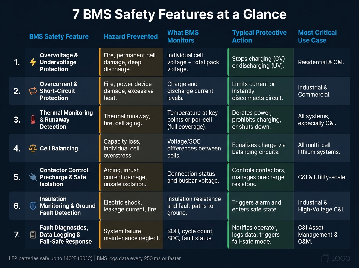
7 Battery Management System Safety Features: Hazards, Monitoring & Actions
Now that the seven protections are defined, it helps to compare them in plain terms. Not every safety feature deals with the same problem. Some stop overcharging. Some cut off fault current. Others watch for heat buildup before it turns into something worse. This table makes that easier to see at a glance.
Thermal protection also covers a range. In some systems, it means a basic shutdown when temperature gets too high. In others, it goes much further, down to per-cell runaway detection.
| BMS Safety Feature | Hazard Prevented | What the BMS Monitors | Typical Protective Action | Most Critical Use Case |
|---|---|---|---|---|
| 1. Overvoltage and Undervoltage Protection | Fire, permanent cell damage, deep discharge | Individual cell and total pack voltage | Stops charging (OV) or discharging (UV) | Residential & C&I |
| 2. Overcurrent and Short-Circuit Protection | Fire, power device damage, excessive heat | Charge and discharge current levels | Limits current or instantly disconnects the circuit | Industrial & Commercial |
| 3. Thermal Monitoring & Runaway Detection | Thermal runaway, fire, cell aging | Temperature at key points or individual cells (full coverage) | Derates power, prohibits charging, or shuts down | All, especially C&I |
| 4. Cell Balancing | Capacity loss, individual cell overstress | Voltage/SOC differences between cells | Equalizes charge across cells via balancing circuits | All multi-cell lithium systems |
| 5. Contactor Control, Precharge, and Safe Isolation | Arcing, inrush current damage, unsafe isolation | Connection status and busbar voltage | Controls contactors and manages precharge resistors | C&I & Utility-scale |
| 6. Insulation Monitoring and Ground Fault Detection | Electric shock, leakage current, fire | Insulation resistance and fault paths to ground | Triggers alarm and enters a safe state | Industrial & High-Voltage C&I |
| 7. Fault Diagnostics, Data Logging, and Fail-Safe Response | System failure, maintenance neglect | SOH, cycle count, SOC, and fault status | Notifies operator, logs data, triggers fail-safe mode | C&I (Asset Management & O&M) |
The next section shows how these seven layers work together as one protection strategy.
How These Features Work Together in One Protection Strategy
These seven protections work like a chain. Voltage limits spot trouble early, thermal checks step in when heat builds, and contactors serve as the last hard shutdown. It all begins with the BMS, which turns live sensor data into safe operating limits.
The BMS keeps the system inside physical safety bounds by constantly sampling cell voltage, pack current, and temperature. It then sets real-time charge and discharge limits based on those readings. Those limits are sent to the inverter/PCS, so the system can throttle output before conditions turn critical. If that control step isn’t enough, the next move is physical isolation.
If EMS control fails, the BMS must override it and open the DC contactors.
Fuses, breakers, and contactors add backup protection at the hardware level. They work on their own, apart from the BMS, but their sizing still depends on the BMS current limits. This layered setup helps the system react fast even if the control software stops doing its job.
Pre-integrated BMS-PCS systems can also cut commissioning delays and improve fault response.
Conclusion
A good BMS does more than track state of charge. It helps protect people, equipment, and battery life. As FFD Power puts it: "For C&I projects, the 'real product' is safety engineering, not just batteries." That’s why these should be the first functions you check when comparing suppliers.
Before you buy, ask for a protection philosophy document and a Single-line Diagram (SLD). The best BMS designs treat safety as the baseline, not an add-on.
FAQs
Which BMS safety feature matters most?
No single safety feature matters most. A Battery Management System relies on several protections working at the same time, plus accurate real-time monitoring, to keep the battery within a safe operating range.
Key functions like overvoltage, undervoltage, overcurrent, and thermal management work together to help prevent fires, permanent damage, and other failures.
How fast should a BMS react to faults?
A Battery Management System (BMS) needs to react to faults very fast to help keep the battery safe. For serious hazards like short circuits, it’s built to cut power almost at once, which helps lower the risk of fire.
It should also keep watching voltage, current, and temperature at all times so it can spot trouble before it gets worse.
What should I check before buying a BMS?
Before you buy a Battery Management System (BMS), make sure it fits your battery chemistry, whether that’s LiFePO4 or NMC, and matches your system voltage. A mismatch here can cause problems fast, so this isn’t the place to guess.
You’ll also want to check the BMS’s continuous current rating. A good rule is to leave 20% to 30% headroom above your peak load. That extra margin helps the system handle demand without running too close to its limit.
Then look at communication. If your setup needs CAN Bus or RS-485, the BMS should support those protocols from the start. On top of that, make sure it includes the core protections you’d expect: overvoltage, undervoltage, thermal management, and cell balancing.