




AC-DC SST Topologies for Power Distribution
If I’m picking an AC-DC solid-state transformer for power distribution, I’d start here: the front end sets grid behavior, the isolation stage sets size and heat limits, and the output stage sets what loads I can serve. Most systems take 4.16 kV to 34.5 kV AC from the feeder and deliver low-voltage AC, 380–1,000 V DC, or both.
In plain terms, this article says three things:
- Multilevel front ends like NPC, CHB, and MMC are often the better fit for medium-voltage feeders because they cut harmonic stress and device voltage stress.
- DAB isolation stages are common when I need bidirectional power flow and about 95%–98% efficiency.
- Two-stage and three-stage SSTs are usually the main choices for sites with EV charging, batteries, PV, data center loads, or mixed AC/DC distribution.
It also points to the main checks before approval:
- feeder voltage match
- DC bus targets
- IEEE 519 harmonic limits
- insulation and 50–100 kV BIL
- cooling and derating
- fault current limits
- service and controls support
Why Solid-State Transformers Could Transform AI Data Centers
sbb-itb-501186b
Quick comparison
| Part of SST | Main options | What I’d check first |
|---|---|---|
| Front end | Two-level, NPC, CHB, MMC | Harmonics, power factor, MV rating |
| Isolation stage | DAB, LLC, isolated full-bridge | Bidirectional flow, soft-switching, heat |
| Architecture | Single-stage, two-stage, three-stage | Port count, control burden, site needs |
| Output | LV AC, 380–400 V DC, 48 V DC, 400–1,000 V DC | Load type, protection, bus ratings |
A simple takeaway: if I only need a fixed output, a single-stage unit may work. If I need a shared DC bus for chargers or storage, a two-stage setup often makes more sense. If I need multiple DC ports plus AC output, I’d look at three-stage designs.
That’s the core of the article, without the extra detail.
Front-End AC-DC Conversion and Grid Interface Topologies
At the grid side, the AFE decides how cleanly an SST connects to the utility and whether it can meet grid rules without trouble. This front end takes three-phase MV AC - usually 4.16 kV, 6.9 kV, 13.2 kV, or 13.8 kV on U.S. distribution feeders - and turns it into a regulated DC link for the isolation stage downstream. To do that, it uses an active front-end (AFE) converter with fast-switching semiconductors, often SiC MOSFETs or IGBTs, to shape input current and hold the DC link steady as load and grid conditions shift. That DC link then sets the isolation stage’s DC voltage, ripple, and transient limits.
Two-Level vs. Multilevel Rectifier Options
At the lower end of MV operation, a two-level PWM rectifier can do the job. The catch is that it creates bigger voltage steps and higher dv/dt, which puts more stress on insulation and usually calls for larger filters to stay within harmonic limits. As voltage goes up into medium-voltage territory, multilevel topologies tend to make more sense. They split the total DC bus voltage across several switching devices, so each device handles only part of the total voltage. That cuts electrical stress and makes MV operation easier.
That’s also why multilevel designs are often chosen when power-factor and THD goals are tight: they can hit those targets with smaller filter stages than two-level setups.
| Topology | Voltage Capability | Harmonic Performance | Efficiency | Scalability | Control Complexity |
|---|---|---|---|---|---|
| Two-Level PWM | Lower MV; requires careful device selection | Lower; needs larger filters | Competitive at lower ratings | Limited | Low |
| NPC | Medium MV | Good; fewer filter stages needed | High | Moderate | Moderate |
| CHB | High MV (13.2 kV and above) | Excellent; near-sinusoidal output | High | Very high; add cells per phase | Moderate–high |
| MMC | High MV; multi-bus capable | Excellent; smooth arm currents | High at large scale | Linear; add submodules | High |
Each multilevel option brings a different tradeoff. NPC works well in the middle range. CHB is a strong fit for higher MV levels because you can stack cells phase by phase. MMC goes a step further and supports multi-bus arrangements with a lot of flexibility on the DC side.
For instance, CHB-based 13.2 kV SSTs can cascade cells per phase and feed isolated DAB stages to produce regulated 750 V DC. MMC-based designs build on that idea by allowing multiple DC bus tapping points from one front end, which helps in multi-port DC distribution architectures.
Performance Targets at the Grid Interface
The front end has to handle several jobs at once: power factor, harmonics, and DC-link control. In U.S. distribution-connected equipment, a power factor of 0.95 or higher across the load range is a main target. The AFE reaches that mark with current-controlled PWM, keeping the input current aligned with the grid voltage.
Harmonics are another big checkpoint. Under IEEE 519-2014 and 2022, voltage THD at the point of common coupling (PCC) must stay below 5% for buses in the 1 kV–69 kV range, and each individual harmonic must stay below 3%. This is where multilevel modulation helps a lot. By building staircase waveforms that track a sine wave more closely, CHB and MMC front ends can cut filter size while still meeting those limits.
The last major task is DC-link regulation. The outer control loop holds the DC bus at its set voltage, while the inner current loop deals with fast transient response. If the load changes all at once, the front end has to absorb that step without letting the DC link dip or jump so much that the downstream DAB or LLC converter falls out of its soft-switching region.
Fault response matters too. The AFE has to spot overcurrent events fast and move into current limiting or blocking, while still coordinating with upstream reclosers and relays. That’s one place where SSTs are more demanding than conventional transformers: they need tighter protection design and relay coordination. That regulated DC link then feeds the isolated DC-DC stage next.
Isolation Stage: High-Frequency DC-DC Conversion and Galvanic Separation
The isolation stage takes the front-end DC link and turns it into a regulated low-voltage DC bus, while also providing galvanic isolation. In practice, it uses a high-frequency transformer (HFT) or medium-frequency transformer (MFT) with a fully controlled DC-DC converter to step medium-voltage DC down to a usable low-voltage DC level. That LV DC bus then serves as the operating point for the downstream DC-DC stage.
The big draw here is switching frequency. When switching frequency goes up, transformer core size goes down, and power density goes up. For buyers, that can mean lighter, smaller distribution hardware. SST isolation transformers usually switch in the tens to hundreds of kilohertz range, while medium-frequency designs often run at 1–10 kHz. Research prototypes have reported volume reductions of 30–70% compared with conventional transformers at similar ratings.
The other major gain is control. Since this stage uses active switches such as SiC MOSFETs or IGBTs around the transformer, the converter can change power flow in real time by adjusting phase shift, duty cycle, or switching frequency. That gives the SST the ability to regulate its DC bus, handle bidirectional power flow, and limit or reroute power faster than a passive transformer.
DAB, LLC, and Other Isolated DC-DC Topologies
The dual active bridge (DAB) is often the go-to option for distribution-level SSTs. It places full-bridge switch networks on both the primary and secondary sides of the HFT, which makes bidirectional power flow fairly direct. Change the phase relationship between the two bridges, and power flow reverses. When the leakage inductance and phase-shift control are tuned for soft-switching, DAB converters can reach about 95–98% efficiency at medium to high power levels. That mix of clean bidirectionality and fairly predictable soft-switching over a broad load range helps explain why DAB shows up so often in MV/LV SST prototypes.
LLC resonant converters work differently. They use a resonant tank made of an inductor, an inductor, and a capacitor to achieve natural zero-voltage switching (ZVS) and zero-current switching (ZCS) near resonance. The payoff is very low switching loss and high power density, with efficiency often reported at 96–98%+ in well-tuned designs. The catch is that the best operating range is tighter. If the input or output voltage moves around a lot, it becomes harder to keep soft-switching and tight regulation at the same time. LLC works well for dense LV modules or modular SST subunits, but pushing it into multi-hundred-kilowatt MV/LV use adds more control challenges.
| Topology | Bidirectional Capability | Typical Efficiency | Soft-Switching | Power Density | SST Suitability |
|---|---|---|---|---|---|
| Dual Active Bridge (DAB) | Native, full bidirectional | ~95–98% | ZVS over a wide load range | High to very high | Excellent for MV/LV distribution |
| Isolated Full-Bridge (phase-shifted) | Usually unidirectional or limited-bidirectional | ~92–96% | ZVS in certain load regions | Moderate to high | Good for simpler or unidirectional modules |
| LLC Resonant | Primarily unidirectional; bidirectional possible but complex | ~96–98%+ | Natural ZVS/ZCS near resonance | Very high | Better for LV modules; more complex at wide MV/LV range |
Once the topology is chosen, the hard part shifts to the transformer itself. Insulation, leakage inductance, and heat limits decide whether the design can handle medium-voltage duty over time.
Transformer Design, Insulation, and Thermal Limits
Turns ratio selection starts with the target LV DC bus. A common target is 750–1,000 V DC for a 480 V AC output after inversion. From there, designers work backward through the converter stages to the MV DC link. For instance, a 13.2 kV AC feeder rectified to a high-voltage DC bus might be stepped down to about 800 V DC on the secondary side, while leaving margin for regulation, transients, and device ratings. SiC switch ratings are often set around 1.2–1.7× the bus voltage.
At medium voltage, insulation coordination is not optional. SST isolation transformers have to meet basic insulation levels in line with standard MV equipment, and design targets of roughly 50–100 kV BIL between the MV and LV sides are common in U.S. distribution use. That puts pressure on winding layout, creepage distance, and encapsulation. The transformer has to survive impulse stress, not just normal operating voltage.
High-frequency switching makes that job tougher because it can create localized high electric field gradients. Those hot spots can trigger partial discharge, and partial discharge can slash transformer life from decades to only a few years if it is left unchecked. Accepted PD limits for MV SST transformers are strict: 10 pC for liquid-immersed designs and 50 pC for dry-type units.
To keep PD in check, engineers lean on void-free vacuum pressure impregnation or cast-resin construction, smooth electrode shapes, and field-grading layers. Leakage inductance is a bit of a double-edged sword. It can cause trouble, but it also helps. DAB and LLC converters rely on a certain amount of leakage inductance to support soft-switching, so winding layout and intentional spacing are tuned together with converter control instead of being pushed as low as possible.
Core material also depends on operating frequency. Ferrite is common for 20–200 kHz, while nanocrystalline or amorphous cores fit 1–10 kHz. Cooling usually comes from forced air, liquid, or dielectric immersion so the unit stays within temperature limits in hot U.S. ambient conditions. Those limits feed directly into LV DC bus design and into the AC or DC output ports that come next.
DC Outputs, Voltage Levels, and Distribution Applications
With a regulated low-voltage DC bus, the SST can feed loads directly and skip an extra line-frequency transformer. That helps turn it into a compact distribution hub. In practice, the output setup shapes two big things: how many loads the SST can serve on its own, and how much extra conversion gear the site still needs downstream.
MV and LV Voltage Levels Common in U.S. Installations
Output voltage is a design decision, not just a list of common rails. In U.S. projects, specifiers usually work across three main DC tiers:
| DC Output Level | Primary DC Bus | Typical Applications |
|---|---|---|
| 380–400 V DC | Primary DC bus | Data centers, commercial buildings, EV charging front ends, microgrids |
| 48 V DC | Branch and auxiliary loads | Telecom, ICT equipment, controls, LED lighting |
| 400–1,000 V DC | High-voltage DC port | EV fast chargers, battery coupling |
The 380–400 V DC range is the most common trunk voltage for building-scale DC distribution. It lines up well with data center and commercial building layouts, and it can be derived with good efficiency from the front-end conversion stage.
The 48 V DC level still matters for telecom and controls because it stays below many safety extra-low-voltage thresholds and matches existing -48 V plant infrastructure.
Each voltage tier fits a different class of load. So the right port mix should follow the site's main distribution job, not just what looks common on paper.
Where DC Output Ports Add Value
Direct DC distribution works best when the equipment downstream is already turning AC into DC inside the device. That’s why a 380 V DC bus makes a lot of sense in data centers. Server racks already rely on internal DC conversion, so feeding them with DC can cut out extra steps. A Lawrence Berkeley National Laboratory demo sent 380 V DC straight to racks and removed several conversion stages. One analysis of a similar setup found 14% CAPEX savings and 28% OPEX savings compared with a legacy 208/120 V AC distribution system.
EV fast charging is another strong use case. A regulated high-voltage DC port from a multiport SST can feed multiple chargers from one shared DC bus, while downstream DC-DC modules handle the vehicle voltage range. On-site batteries or PV can tie into that same bus for peak shaving without passing through extra AC stages. At telecom sites and edge locations, a dedicated 48 V DC port can feed existing -48 V plant with very little conversion overhead.
Multiport SST designs push this a step further by providing separately controlled DC ports at different voltage levels:
- MVDC for battery strings or PV
- LVDC at 380–400 V for building loads
- 48 V auxiliary rails for controls
Each port can have its own protection, power limits, and control profile. That separation helps with fault isolation, so a fault on one DC bus does not spread to another when the ports are properly isolated. That’s the difference between a single-output converter and a node that can serve several load types at once.
Sourcing Related Distribution Equipment
The SST does the core conversion, but the rest of the distribution setup still relies on standard gear around it. That includes MV switchgear, pad-mounted or dry-type transformers for non-SST feeders, DC-rated breakers for low-voltage DC buses, and LV panelboards for mixed AC/DC loads.
DC-rated protection devices need close attention. Standard AC breakers are not tested for DC interruption duty, so buyers need to verify that every breaker and disconnect on a DC bus is rated for the actual bus voltage.
Electrical Trader can centralize procurement of breakers, transformers, and DC-rated protection devices for the surrounding distribution gear.
Design Tradeoffs and a Specification Checklist for Buyers
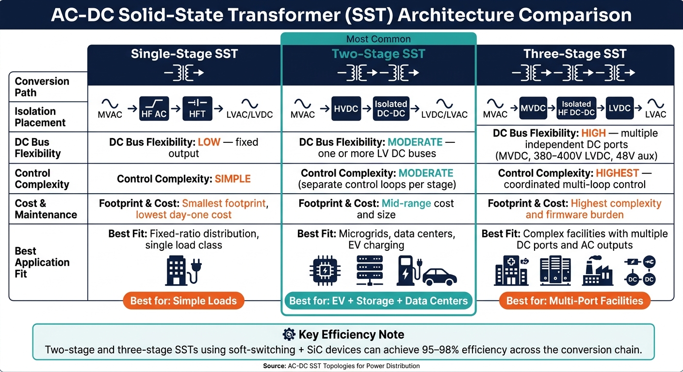
AC-DC SST Architecture Comparison: Single-Stage vs Two-Stage vs Three-Stage
Single-Stage, Two-Stage, and Three-Stage SST Architectures Compared
Once the front end, isolation stage, and output ports are set, the last step is choosing the architecture that fits your budget, operating needs, and service model. In plain English: the “best” SST setup depends on feeder voltage, output demands, and what your team can support over time.
Here’s the side-by-side view:
| Architecture | Conversion Path | Isolation Placement | DC Bus Flexibility | Control Complexity | Best Fit |
|---|---|---|---|---|---|
| Single-stage | MVAC → HF AC → HFT → LVAC/LVDC | Integrated into the main conversion stage | Low - fixed output set | Simpler control | Fixed-ratio distribution, single load class |
| Two-stage | MVAC → HVDC front-end → isolated DC-DC → LVDC/LVAC | Between the HV DC link and the LV DC bus | Moderate - one or more LV DC buses | Separate control loops per stage | Microgrids, data centers, and EV charging |
| Three-stage | MVAC → MVDC → isolated HF DC-DC → LVDC → LVAC | In the isolated DC-DC stage | High - multiple independent DC ports | Highest; coordinated multi-loop control | Complex facilities with multiple DC ports and AC outputs |
Each option gives you something different.
Single-stage designs stand out for smaller footprint and lower day-one cost. They make sense when the output set is fixed and the load profile is narrow.
Three-stage designs give you the most flexibility. If a site needs several DC ports plus AC output, this setup gives you more room to shape the system around the load.
Two-stage systems often land in the middle in a good way. They give more output freedom than single-stage designs without the added firmware and controls burden that comes with three-stage systems. And when two-stage and three-stage SSTs use soft-switching and SiC devices, they can still hit very high efficiency.
One tradeoff matters more than many buyers first expect: maintenance. A three-stage system needs firmware coordination across several control loops. That means architecture choice isn’t just about efficiency numbers on a datasheet. It also has to match the skill set your team already has in-house. A system that looks great on paper can become a headache if no one wants to own the controls stack.
What to Check Before Approving an SST Specification
After you pick the topology, the next step is simple: check the spec against the feeder, the load, and the service conditions you’ll see in the field. This is where a lot of costly mistakes start - or get avoided.
Buyers should confirm:
- Power rating: Match the continuous rating to both peak and average facility load. Also check short-term overload capability. SSTs are semiconductor-limited and cannot match the fault current margins of conventional MV transformers. Fast protection and current limiting are a must.
- MV and LV voltage class: Make sure the SST lines up with feeder voltage and the output voltage the site needs.
- DC bus setpoints and regulation: Define nominal DC levels and allowed tolerance during load transients.
- Efficiency across load range: Ask for efficiency curves at 25%, 50%, 75%, and 100% load.
- Harmonic compliance: Confirm IEEE 519 compliance at the MV interface without relying on oversized external filters.
- Thermal management: Review the cooling method and ambient-temperature derating curves.
- Insulation and BIL: Check basic insulation level, creepage distances, and compliance with applicable U.S. standards.
- Documentation and service support: Confirm that commissioning steps, training, and remote diagnostics are included - or at least priced clearly.
This part is less glamorous than topology diagrams, but it’s where buyers protect themselves. If the load swings hard, if the site runs hot, or if service support is vague, those details come back later.
Key Points for Selecting an AC-DC SST Topology
The right pick comes down to balancing grid performance, insulation needs, and fit for the job.
- Front end: Determines grid performance and harmonic margin.
- Isolation stage: Determines size, safety, and thermal limits.
- Output ports: Determine application fit and port flexibility.
- Total project fit: A two-stage SST is often the better lifecycle choice when a three-stage system’s added flexibility isn’t needed, because it costs less up front and is easier to maintain over time.
FAQs
Which SST topology best fits my site?
The right solid-state transformer (SST) topology comes down to a few practical factors: your grid interface, the load, whether you need isolation, and how much heat the system can handle.
For medium-voltage grid interfaces, modular multilevel converters and cascaded H-bridge topologies are often the go-to options. Why? They scale well, and they’re easier to service when compared with more monolithic designs.
For isolated DC-DC conversion, the dual-active bridge is a common pick.
Isolation is one of the big decision points here. If you need ground separation for safety or noise control, use isolated topologies like flyback or forward. If the system shares a common ground, non-isolated buck or boost regulators are usually more efficient.
When should I choose DAB over LLC?
In SST designs, choose DAB for the isolated DC-DC conversion stage in the power distribution system. It’s the standard pick for this part of the stack because it supports compact, high-frequency power transfer between SST stages.
Other topologies, such as MMC or cascaded H-bridge converters, handle different grid-interface roles. DAB is used specifically for the isolated DC-DC link.
What should I verify before buying an SST?
Before you buy a solid-state transformer (SST), make sure your current setup can handle it. That means checking whether the feeder voltage, switchgear, protection settings, and cooling all line up with the unit you plan to install.
You’ll also want to look at fault behavior. An SST can change how faults show up in the system, which may mean you need to adjust relay coordination and update DC fault-clearing methods. If you skip that step, problems can show up later when the system is under stress.
Then move to the nameplate and spec sheet. Check the kVA rating, voltage levels, 60 Hz frequency, phase configuration, %Z, and cooling class. These details tell you whether the transformer fits your site or whether it’s going to be a square peg in a round hole.
Last part: ask for the paperwork. Request test reports, and confirm the unit meets the relevant IEEE, UL, or DOE requirements.





