




UPS Integration with Facility Management Systems
If your UPS is not tied into the system your team already watches, you may not know there is a power problem until equipment drops. In U.S. hospitals, data centers, plants, and control rooms, the main job is simple: get UPS status, battery health, runtime, and alarms into one place, then test that path before you rely on it. That matters because UPS failure is linked to about 42% of power-related data center outages.
Here’s the short version:
- I start by deciding monitoring only or monitoring plus control
- I send UPS data to the platform staff already use: BMS, SCADA, DCIM, or CMMS
- I match the UPS protocol to that platform: SNMP, Modbus RTU, Modbus TCP, BACnet, or dry contacts
- I define the point list first: input/output power, load, battery charge, runtime, temperature, mode, and alarms
- I set alarm levels so only load-risk events become critical
- I build the data path with clean IP or RS-485 setup
- I test utility loss, overload, comm loss, timestamps, and alarm delivery before sign-off
A few details drive most of the result:
- SNMP fits DCIM and IT monitoring
- Modbus RTU fits SCADA and long RS-485 runs
- Modbus TCP fits Ethernet-based SCADA or BMS
- BACnet fits BMS
- Dry contacts fit simple alarm-only needs
For setup, I keep:
- Static IPs
- OT VLANs
- Only the needed ports open
- SNMPv3 authPriv for SNMP
- RS-485 trunks terminated only at both ends with 120 Ω
- Cable runs clear of high-voltage feeders and VFDs
For monitoring, I keep naming and units consistent, such as:
- Volts
- Amps
- Hz
- kVA / kW
- Percent
- °F
- Minutes
A small comparison helps show the fit:
| Method | Best Use | What You Get |
|---|---|---|
| SNMP | DCIM, NMS, IT rooms | Status polling + traps |
| Modbus RTU | SCADA, PLC, plants | Register polling over RS-485 |
| Modbus TCP | Ethernet-based BMS/SCADA | Register polling over LAN |
| BACnet | BMS | Objects, polling, COV |
| Dry contacts | Legacy panels, simple alarms | Basic discrete states only |
Bottom line: I would treat UPS integration as a power-risk project, not just a comms task. The article shows how to choose the platform, protocol, point list, alarm rules, network path, and test steps so staff can see trouble early and act before the load is at risk.
CyberPower RMCARD205: Seamless Remote Management for Your UPS Systems
sbb-itb-501186b
Choose the Right Communication Method
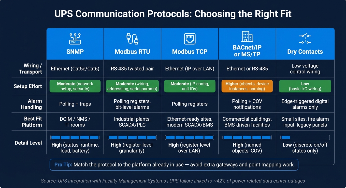
UPS Communication Protocols Compared: SNMP, Modbus, BACnet & Dry Contacts
Once the destination platform is set, pick the protocol it already supports. That choice affects alarm speed, point depth, wiring, and day-to-day upkeep. For critical sites, the best option is the one that lines up with the site's network rules, support team, and alarm response flow. After you lock in the transport, define the exact UPS points and alarm priorities the facility system will read.
UPS Interfaces: SNMP, Modbus RTU, Modbus TCP, BACnet, and Dry Contacts
Many three-phase UPS units support SNMP, Modbus, BACnet, and dry contacts through a communication card.
Here’s how each interface is usually used in U.S. facilities:
- SNMP uses Ethernet and is common in data centers and IT rooms. DCIM and network management tools poll UPS status, battery runtime, and load over IP, and they receive SNMP traps when alarms fire.
- Modbus RTU runs on RS-485 twisted pair and is common in industrial plants and electrical rooms. It ties straight into SCADA and PLC systems with multi-drop wiring for long RS-485 runs.
- Modbus TCP uses the same Modbus register model over standard Ethernet, so it fits newer sites where most systems already run on IP.
- BACnet - BACnet/IP or BACnet MS/TP - is common in BMS installations. UPS data shows up as BACnet objects, polled or pushed through COV notifications, either natively or through a Modbus-to-BACnet gateway.
- Dry contacts are the simplest path: relay outputs wired straight to PLC or BMS digital inputs. They carry only discrete alarms, like on battery or general fault. That makes them useful for legacy panels or fire alarm interfaces, but you get far less detail than with a data protocol.
How Facility Systems Consume UPS Data
Each platform reads UPS data a little differently, so the protocol needs to match the platform’s polling and alarm model.
SCADA systems usually poll Modbus registers on a fixed cycle, often every 1 to 5 seconds, and check bit flags or register values to trigger alarms. Engineers map each register to a SCADA tag by hand, such as battery voltage, output kW, or alarm status.
BMS platforms work in much the same way with Modbus. When BACnet is used, UPS conditions appear as named objects, such as UPS Output kW or UPS Status, that the BMS can poll or receive through COV notifications. COV means the UPS sends an update to the BMS as soon as a value changes instead of waiting for the next poll.
DCIM and IT monitoring tools depend on SNMP polling for routine status checks, along with traps for near-real-time alerts. If a UPS switches to battery or detects an overload, it sends a trap to the DCIM platform at once, and that can trigger a ticket or escalation. From there, the focus shifts to which points are important enough to alarm.
Protocol Selection by Application
The protocol should follow the platform already in use. Match the protocol to the receiving platform so you don’t add extra gateways and point mapping work.
| Protocol | Wiring | Setup Effort | Alarm Handling | Best Fit |
|---|---|---|---|---|
| SNMP | Ethernet (Cat5e/Cat6) | Moderate (network setup, security) | Polling + traps | Data centers, IT rooms, DCIM/NMS |
| Modbus RTU | RS-485 twisted pair | Moderate (wiring, addressing, serial params) | Polling registers, bit-level alarms | Industrial plants, electrical rooms, SCADA/PLC |
| Modbus TCP | Ethernet (IP over LAN) | Moderate (IP config, unit IDs) | Polling registers | Ethernet-ready sites, modern SCADA/BMS |
| BACnet/IP or MS/TP | Ethernet or RS-485 | Higher (objects, device instances, naming) | Polling + COV notifications | Commercial buildings, campuses, BMS-driven facilities |
| Dry contacts | Low-voltage control wiring | Low (basic I/O wiring) | Edge-triggered digital alarms | Small sites, fire alarm input, legacy panels |
Many critical sites keep UPS traffic on isolated RS-485 trunks, such as Modbus RTU or BACnet MS/TP, instead of placing UPS devices straight on the corporate IP network. A simple rule helps here: use one detailed path for operations, and a second, simpler path only when another team needs it.
With the protocol and transport fixed, the next step is mapping UPS points and alarm levels.
Define Monitoring Points and Alarm Mapping
Document every UPS point and alarm before you touch the software. That simple step keeps units consistent, fills in missing points early, and makes alarms far less messy during commissioning.
Core UPS Points to Monitor
Split UPS monitoring points into three groups: power path, battery, and operating status.
For the power path, include:
- Input voltage and current for each phase
- Input and output frequency
- Output voltage and current for each phase
- Output kVA and kW
- Load percentage
For the battery, monitor:
- State of charge (%)
- Battery temperature in °F
- Remaining runtime in minutes
For operating status, track whether the UPS is in normal, battery, bypass, eco-mode, test, or fault.
You’ll also want charger status, inverter status, static bypass status, battery health status such as good, degraded, or replace, plus the last battery test result and timestamp. Those points help teams spot battery wear early and catch unwanted operating states, especially eco-mode.
Use one naming convention across every UPS on site. A tag like BLDG1_UPS1_Batt_Temp_degF tells operators and technicians exactly what they’re looking at. Keep U.S. engineering units the same everywhere: volts, amps, Hz, kVA, percent, °F, and minutes. And keep all temperatures in °F to prevent misreads in the control room.
Use this list to build the alarm matrix below.
Alarm Mapping and Priority Levels
Most UPS changes should stay informational. Save critical alarms for conditions that put the load at risk. Each monitored point should map to a clear trigger.
| Severity | Example UPS Alarms | Operational Impact | Recommended Action |
|---|---|---|---|
| Informational | Battery test completed, UPS in eco-mode | No immediate risk; expected state changes | Acknowledge and log; verify expected behavior |
| Warning | Battery temperature high, battery health degraded, input voltage slightly out of range | Developing issue; not yet an emergency | Check cooling, review trends, plan maintenance |
| Critical | UPS on battery with low runtime, overload, bypass active with inverter fault, output off, communication lost to UPS | Immediate or imminent risk to critical loads | Execute emergency procedures, shed noncritical loads, dispatch technician |
Build a UPS Point List and Alarm Matrix
Write down every point before software configuration starts. For each one, record the tag name, description, protocol address such as Modbus register number, SNMP OID, or BACnet object ID, data type, scaling, units, normal operating range, polling rate, alarm thresholds, and alarm priority.
Polling rate matters more than people think. Status points like operating mode or on-battery state can poll every 5 to 15 seconds. Trend points like battery temperature or load percentage can poll every 30 to 60 seconds and still give you the detail you need.
The alarm matrix should connect each alarm to:
- Its trigger condition
- Its severity level
- Its expected response time
- Its required action
- Its owner
Each alarm should lead to one clear action, one owner, and one response time. That keeps this section in line with the site’s critical-infrastructure response rules. For example: Batt_Temp_degF > 95°F for 5 minutes.
During commissioning, this matrix becomes the working checklist. Technicians simulate each condition, confirm that the facility system shows the right alarm text and priority, and verify that notifications reach the right people. After go-live, the same matrix supports annual alarm reviews and threshold tuning.
Design Data Flow and Network Setup
Once the point list and alarm matrix are set, the next job is to map the path that carries UPS data to the facility platform. At this stage, the goal is simple: choose the shortest dependable path from the UPS to the system that will read it.
Common Data Flow Patterns for Critical Sites
Most critical sites use one of four patterns:
- UPS → Ethernet card → BMS over Modbus TCP: The BMS polls the UPS directly. There’s no gateway in the middle, which keeps the setup simple and makes it easier to scale across many UPS units.
- UPS → RS-485 bus → SCADA over Modbus RTU: Multiple UPS units daisy-chain into a PLC or RTU, which then feeds the SCADA HMI. This setup fits long cable runs and electrically noisy spaces, as long as the RS-485 wiring is done right.
- UPS → SNMP network card → DCIM or NMS: This is common in IT-run data centers. It keeps UPS alarms in the same monitoring stack as the rest of the IT gear.
- UPS → gateway → BACnet/IP: Use a gateway when direct integration isn’t available, or when several downstream systems need different protocols.
Some sites also run parallel BMS and DCIM paths from the same UPS card.
Once the path is picked, lock down the details that make or break uptime: addressing, segmentation, and bus wiring.
Network and RS-485 Setup Details That Affect Reliability
These settings help avoid missed polls, failed traps, and flaky serial links. For Ethernet-based setups, three choices matter most: addressing, segmentation, and wiring.
Assign static IPs, place UPS devices on OT VLANs, and allow only the ports you need:
- TCP 502 for Modbus TCP
- UDP 161/162 for SNMP
- UDP 47808 for BACnet/IP
Document those rules and test them during commissioning so polling and trap delivery work the way they should.
For SNMP, use SNMPv3 authPriv, set unique credentials for each environment, and place devices on a management VLAN that only monitoring servers can reach. SNMPv1 and SNMPv2c send community strings in plaintext, which is a risk you don’t need.
On the RS-485 side, reliability comes down to clean wiring habits. Use shielded twisted pair, terminate only at both ends of the trunk with 120 Ω resistors, ground the shield at one point, and check for about 60 Ω across the bus with power off.
Keep stubs short. Also keep RS-485 cable away from high-voltage feeders and VFDs. A good rule of thumb is to keep cable length × baud rate at or below 10^8 - roughly 4,000 ft at 9,600 baud.
With the data path stable, the next step is install, mapping, and commissioning.
Implement, Test, and Maintain the Integration
Implementation Workflow: From Hardware Install to Point Mapping
Once the point list, alarm matrix, and data path are set, it’s time to install the hardware and check the mapping. Start by confirming the exact UPS make, model, and firmware revision, plus the communication protocols it supports. Register maps and MIB files can change by firmware version, and even a small mismatch can throw off scaling.
Install the correct network management card or gateway based on the manufacturer’s instructions. That includes any required ESD precautions and power-down steps. After the card is in place, connect Ethernet to the assigned switch port or VLAN, or run the RS-485 twisted-pair to the bus trunk. Label every cable and port before you move on. This is the point where the earlier point list and alarm matrix start becoming live, checked data.
Next, set the device ID, credentials, time sync, and point map. Then verify scaling and units in the facility platform. Set the site time zone and make sure timestamps display as MM/DD/YYYY HH:MM.
After the device is mapped, test alarms in the same sequence operators will see them.
Commissioning Tests and Acceptance Checks
Commissioning will either confirm the integration works or expose mapping mistakes. The best way to handle it is with a structured test sequence and a written pass/fail record for each item.
Start with a baseline reading check. Compare mapped points to the UPS front panel for input voltage, output voltage, load, battery charge, and internal temperature under normal operating conditions. If anything doesn’t match, you’re likely dealing with a scaling or unit problem, and that needs to be fixed before anything else.
Next, trigger a benign event, such as a battery test. Then confirm the event timestamp in the facility system matches the UPS log within ±1 minute, displayed as, for example, 09/16/2026 14:30.
Then test these four scenarios:
| Test Scenario | What to Verify |
|---|---|
| Simulated utility loss / battery mode | UPS mode updates in the facility system within the polling interval; critical alarm fires; notifications reach designated recipients |
| Overload alarm | Alarm triggers at manufacturer-defined threshold; correct priority level is displayed; escalation path activates |
| Communication failure | Facility system detects loss, logs the event, and issues a communication alarm without flooding operators |
| Recovery | System returns to normal, alarms clear appropriately, and recovery events are logged |
Each test entry in the commissioning checklist should include:
- Test date (MM/DD/YYYY)
- Technician’s name
- Clear pass or fail result
If a test fails, log the corrective action and run the test again before sign-off.
Conclusion: What a Successful UPS Integration Should Deliver
If those checks pass, the integration is ready for operations. A good UPS integration gives operators accurate status, alarms, and runtime data through a tested, reliable path, without forcing manual front-panel checks.
That result comes from a clear objective, the right protocol, a complete point list, a stable network path, and commissioning tests that show each part works under realistic conditions.
FAQs
Which UPS protocol should I use?
Choose the protocol based on what you need the system to do and how complex the setup is.
BACnet works well for large, multi-vendor building automation systems. It supports peer-to-peer communication, automatic device discovery, and an object-based model that helps different devices work together more smoothly.
Modbus is often a better fit for simpler, register-based monitoring. But there’s a tradeoff: it usually needs manual mapping, and it doesn’t include native security.
If you’re dealing with enterprise or industrial integration and need richer semantic models or cloud analytics, look at OPC UA or MQTT. And if a site uses a mix of protocols, gateways can connect them.
What UPS alarms should be critical?
For critical sites, prioritize UPS alarms based on how much they affect system integrity and site safety.
Critical alarms usually include:
- Over-demand events
- Power factor issues
- Load spikes
- Overcurrent events
- Breaker trips
- Overheating
- Smoke
- Water presence
- High humidity
- Battery health issues, including individual cell voltage diagnostics
It helps to use a tiered alarm structure so teams can tell at a glance what needs immediate action and what can wait. Then connect those alarm thresholds to your CMMS so the system can trigger automated work orders as soon as a set limit is hit.
How often should UPS integrations be tested?
Test UPS integrations on a set schedule, especially after network expansions or firmware updates. That helps keep data clean and the system running the way you expect.
Review event, audit, and firmware logs monthly to catch failures or stale data. Annually, check mapped points against the physical device, confirm meter calibration, and inspect wiring. For new integrations, watch data stability for 30 to 60 days before turning on full automation.





