




Underground Cable Installation Equipment Guide
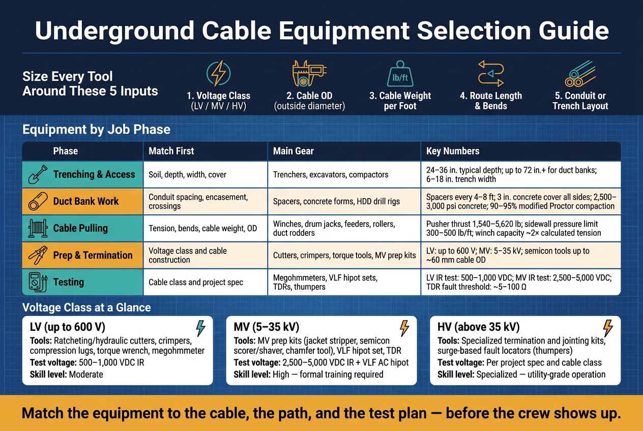
If you choose underground cable equipment by guesswork, you can damage cable before the system is even energized. I’d size every tool around five inputs: voltage class, cable OD, cable weight per foot, route length/bends, and conduit or trench layout. That covers the full job: trenching, duct bank setup, access points, pulling, terminations, and testing.
Here’s the short version:
- Direct-buried runs need trenching and backfill gear.
- Duct banks add spacers, concrete cover, compaction, and in some cases HDD tools.
- Manholes and vaults need entry protection, rollers, rigging, and access gear.
- Pulling gear must stay within cable tension and sidewall pressure limits.
- LV and MV work use different prep and test tools.
- Used gear can work, but only after checking wear, brakes, hydraulics, and calibration records.
A few numbers shape most buying decisions:
- Trenches can run 24–36 in. deep for many buried circuits, with some trenchers going 72 in.+
- Duct spacers are often set every 4–8 ft
- Concrete cover is often 3 in. on all sides
- Backfill compaction is often 90%–95% modified Proctor
- Cable pushers can add about 1,540–5,620 lb of thrust
- MV cable prep usually applies to 5 kV–35 kV systems
- LV IR testing often uses 500–1,000 VDC, while MV IR testing often uses 2,500–5,000 VDC
If I had to boil the guide down to one point, it would be this: match the equipment to the cable, the path, and the test plan before the crew shows up.
| Part of the job | What to match first | Main gear |
|---|---|---|
| Trenching/access | Soil, depth, width, cover | Trenchers, excavators, compactors, ladders |
| Duct bank work | Conduit spacing, encasement, crossings | Spacers, concrete setup, HDD tools |
| Pulling | Tension, bends, cable weight, OD | Winches, jacks, trailers, feeders, rollers |
| Prep/termination | Voltage class and cable construction | Cutters, crimpers, torque tools, MV prep kits |
| Testing | Cable class and project spec | Megohmmeters, VLF sets, TDRs, thumpers |
This guide is for U.S. contractors, electricians, facility teams, and buyers who want a simple way to pick the right underground cable equipment without missing load limits, bend limits, or test requirements.
Underground Cable Equipment Selection Guide by Voltage Class & Job Phase
Underground Electric Install Part 3 | Pulling Wire with an electric cable puller
sbb-itb-501186b
Trenching, Duct Bank, and Access Equipment
Before cable pulling starts, the route has to be ready. That means using excavation tools, duct bank gear, and access equipment that fit the job. Direct-buried runs depend on trenching equipment. Duct bank routes add spacers, concrete, and boring tools.
Excavation and trench preparation tools
Tool selection starts with soil conditions and the shape of the trench. Ride-on chain trenchers can cut trenches 6–18 in. wide and 72 in. or more deep for duct bank runs. Walk-behind chain trenchers fit many utility and electrical conduit jobs, usually 18–36 in. deep, with larger models reaching 48 in.
When trench width shifts or vault access is tight, mini-excavators or backhoes are often the better pick. 12–24 in. buckets fit single-conduit runs or smaller duct banks, while 24–36 in. buckets work better for larger banks.
Vibratory plows make sense in soft, uniform soils where keeping surface disruption low matters, like turf or landscaped areas. They cut a narrow slit that is often 2–6 in. wide. Microtrenching goes narrower still, usually about 1–2 in. wide and 12–24 in. deep along road edges or sidewalks for permitted shallow low-voltage circuits. In both cases, the big upside is less restoration work and less traffic disruption than open-cut trenching.
Code rules also affect equipment choice. Excavations 5 ft or deeper need a protective system unless the cut is in stable rock. Ladders, spoil pile setbacks, and access spacing also need to be planned before digging starts.
Once the trench is open, the job shifts from excavation to conduit spacing, alignment, and encasement.
Duct bank construction and directional boring equipment
Duct bank work comes down to spacing, alignment, and concrete cover. Plastic or steel spacers are usually placed every 4–8 ft to keep ducts 3 in. or more apart and stop sagging during concrete encasement. Factory-made snap-lock spacers with built-in rebar tie points are showing up more often because they speed up setup and help keep the run straight. Many standards also call for 3 in. of concrete cover on all sides.
For encasement, many specs call for concrete with 2,500–3,000 psi compressive strength at 28 days, using 3/4-in. aggregate and about a 6-in. slump so the mix can flow around conduits without leaving voids. Backfill is often compacted with plate compactors, rammers, or vibratory compactors to about 90–95% modified Proctor density under pavement or structures. When a duct bank passes under roads with less than 30 in. of earth cover, many standards call for #4 rebar or a similar reinforcing method to carry live loads.
For road crossings and other paved obstacles, HDD uses a drill rig along with fluid mixing and tracking equipment. Smaller rigs are often enough for 2–4 in. conduits on short crossings. Larger rigs, paired with backreamers, can handle multi-duct bundles. Entry and exit angles usually fall between 8 and 15 degrees, and the pilot bore is then enlarged with progressively bigger reamers until it reaches final size. On short, single-conduit crossings, pneumatic piercing tools can be the faster option because they push soil aside instead of drilling it.
Access structures bring in another layer of cable protection at each pull point.
Manhole, vault, and duct entry protection gear
At every access point, entry hardware helps protect the cable. Bellmouths should be installed at duct entries, and rollers should be placed at the opening to reduce edge damage and lower sidewall pressure. These parts need to be in place and checked before the pull starts.
Inside the structure, rated shackles, swivels, slings, and sheaves help guide pulling force around bends and connect cable grips to winch lines. Workers use portable or fixed ladders for access, and tripod-mounted davit hoists help lift heavy cable sections or splice assemblies. That matters even more on medium- and high-voltage work, where cable weight adds up fast.
PPE at access points should match the task:
- For energized or maybe-energized structures, use voltage-rated gloves, arc-rated clothing, and temporary grounding sets matched to the system and its fault duty.
- For trenching and duct bank work, use hard hats, safety glasses, hi-vis vests, steel-toe boots, cut-resistant gloves, and dust protection when needed.
With the route prepared, the next step is pulling equipment sized for cable weight, tension, and bend limits.
Cable Handling and Pulling Equipment
The focus now moves to pull-path control. Pulling equipment needs to match the cable’s weight, the route length, the number of bends, and the cable’s allowable tension. Each tool handles a different part of the job. Direct-buried runs usually rely more on feeders and rollers. Conduit and manhole pulls lean more on winches, jacks, and rodders.
Winches, drum trailers, jacks, and cable feeders
A cable winch is the main pulling tool for most underground cable pulls. Use a winch with a calibrated tension display, or pair it with an in-line dynamometer, so you can watch pulling force in real time and stay within the cable maker’s limits. Size the winch for the worst-case pull force on the route, then add a safety margin. One detail can trip people up: winch pull ratings drop as rope builds up on the drum. So the number that matters is the rating at the actual rope layer you’ll be using.
Drum trailers and drum jacks hold and pay out heavy cable reels during the pull. The right size depends on reel weight, reel diameter, barrel width, and reel axle fit. On long conduit runs or routes with several bends, a cable pusher or feeder at the feed end can take some strain off the winch and cut sidewall pressure. Mid-range pushers deliver about 1,540 to 1,985 lb of thrust at 20 to 26 ft/min for cable diameters from roughly 1.2 to 7.1 in. Utility-grade pushers can reach up to 5,620 lb of maximum pulling tension at about 56 ft/min, and they handle conductors from about 2 to 7.9 in. in diameter.
Rollers, pulling grips, guides, and duct rodders
Once the reel starts turning, path control becomes the big concern. Rollers and guides keep the cable away from sharp edges and steer it through the trench, vault, or duct. Straight-line rollers work on long, direct sections to cut drag. Corner rollers and quadrant blocks handle direction changes at manholes, vaults, or duct transitions. Feed tubes and bellmouths smooth the move from reel to duct at conduit entries. The more bends in the route, the more friction you get, which means roller spacing matters even more.
Pulling grips - also called basket grips or cable socks - hold the cable jacket during the pull. Basket grips over non-leaded jackets are often limited to about 1,000 lb. Pulling eyes connect to conductors and can handle up to 10,000 lb, or the maker’s stated rating, whichever is lower. Many 600 V and medium-voltage cables limit sidewall pressure to 300 to 500 lb/ft. Interlocked armored cable is often limited to 300 lb/ft. A swivel placed between the grip and the wire rope helps stop torsion from twisting the cable or damaging shields during the pull. And this part is simple but important: every piece in the pulling string - shackles, swivels, wire rope, and grips - should be rated for the full pulling load.
Fiberglass duct rodders come into play before the cable goes in. They’re used to probe and clear conduit runs, check duct continuity, and install a pilot line for the pulling rope. Common U.S. products include 600 ft × 1/4 in. traceable fiberglass rodders that weigh around 49 lb. Prices run from about $115.90 to $1,800.00, depending on diameter and brand. On longer utility pulls, the rodder gets the duct ready first, while powered equipment does the actual cable movement.
Pulling equipment comparison by use case and capacity
| Equipment | Typical Capacity | Best-Fit Installation | Main Advantage | Key Buying Limit |
|---|---|---|---|---|
| Cable winch | Route-dependent; high-capacity units for utility-scale pulls | Duct bank, conduit, trench | Primary pulling force; tension-monitored models available | Capacity drops at higher rope layers on drum |
| Cable pusher/feeder | About 1,540–5,620 lb of thrust | Duct bank, trenchless | Reduces winch load; lowers sidewall pressure | Limited to the cable diameter range of the unit |
| Rollers (straight/corner) | Friction control only | All installation types | Protects sheath; reduces drag at bends | Must be sized and spaced for cable outside diameter and bend radius |
| Duct rodder | Pilot-line setup only | Conduit verification and setup | Confirms duct continuity; installs pull line | Not a pulling tool; limited by conduit length and bend count |
Once the pull is done, the work shifts from moving cable to getting it ready for termination and testing.
Jointing, Termination, and Testing Equipment
Once the pull is done, the job moves into prep, termination, and proof testing. This is the stage where crews find pull damage, check that terminations were made correctly, and confirm the insulation is still fit for service before energization. And the tool set changes fast with voltage class. A 600 V feeder setup is not the right fit for a 15 kV shielded cable.
Cable preparation and termination tools by voltage class
For low-voltage (LV) work up to 600 V, the main tool set usually includes ratcheting or hydraulic cable cutters, insulation strippers, crimpers, compression or mechanical lugs, and a calibrated torque wrench. Hydraulic cutters and crimpers are standard on larger conductors, including 1/0 to 500 kcmil feeders, where manual tools simply don’t have enough jaw capacity or force. Dieless hydraulic crimpers handle a broad range of AWG and kcmil sizes without constant die swaps, which saves time in the field.
In underground vaults and manholes, battery-powered cutters and crimpers are often easier to handle than corded or bulkier gear. Lugs and connectors should be UL-listed and rated for damp locations, such as NEMA 3R or 4X, when they’re used below grade.
MV cable prep takes more time and a lot more care because shield layers have to come off in the right order. Medium-voltage (MV) cable preparation is more exacting and procedure-driven. Shielded cables in the 5 kV–35 kV range include an outer jacket, shield layers, semicon screens, and thick XLPE or EPR insulation. Each layer must be removed in a set sequence and to exact dimensions.
That’s why purpose-built MV prep kits matter. These kits group together jacket strippers, semicon scorers, semicon shavers, insulation removal tools, and chamfer tools sized for given cable diameters. Some semicon tools can remove bonded semiconductor shields from XLPE or EPR cables up to about 60 mm in diameter without lubrication, while leaving a smooth cutback that helps reduce electric stress.
Using a knife instead of the right prep tool might seem like a shortcut, but it can nick the insulation. That small mistake can turn into partial discharge and then early failure in service. MV tools have to match the jacket thickness, shield type, and cable diameter. If they don’t, the termination may fail long before it should.
Field testing and fault location equipment
Before energization, testing checks whether the installation is sound. It confirms the cable, the terminations, and the pull path all made it through installation without damage.
For new LV installations, the standard setup is an insulation resistance (IR) test with a megohmmeter, usually at 500 to 1,000 VDC, along with continuity checks using a multimeter. IEEE guidance calls for a minimum test voltage of 500 VDC for LV cables, with acceptable resistance often stated as R (MΩ) = (rated kV + 1) × 1,000 / cable length in feet. These tests are meant to catch major faults before the panel is energized, such as shorts, low insulation resistance from moisture, or damage from pulling.
MV cable systems require more rigorous testing. After jointing and termination, utilities and industrial sites often use VLF (very low frequency) AC hipot test sets to stress the insulation at a set multiple of rated voltage, following IEEE 400 and IEEE 400.2 guidelines. IR tests are still used on MV cables, but at higher voltages - usually 2,500 to 5,000 VDC - and the results are read alongside cable length and insulation thickness.
Jacket integrity tests also come into play on shielded MV cables. These tests check outer sheath resistance to ground and can spot damage or water ingress before it turns into neutral corrosion. Sheath and insulation test voltages depend on the project spec and the cable class.
For fault location on existing cables, the main tools are TDRs (time-domain reflectometers) and surge-based fault locators. A TDR sends a pulse down the cable and reads the reflected signal to estimate the distance to an impedance change. That makes it useful for finding opens, shorts, or splice issues. If fault resistance is too high for a TDR - roughly above 5 to 100 Ω depending on the method - a surge generator, or thumper, sends a high-energy pulse into the cable, and the fault arc is then found acoustically or electrically in the field.
Testing and preparation equipment comparison
| Equipment | Voltage Range | Primary Task | Skill Level | Portability | Typical Buyer |
|---|---|---|---|---|---|
| LV termination tools (cutters, crimpers, torque tools) | Up to 600 V | Cut, strip, crimp, torque conductors and lugs | Moderate | Portable; battery-powered preferred for vaults | Electrical contractors, facility maintenance |
| MV cable prep kits | 5 kV–35 kV | Jacket, shield, and semicon removal; insulation chamfering | High; formal training required | Portable hand tool kits | Utilities, cable contractors, industrial plants |
| Insulation resistance tester (megohmmeter) | 250 V to 5 kV DC output | IR testing conductor-to-ground and conductor-to-conductor | Moderate | Handheld or small case; highly portable | Contractors, service technicians, plant maintenance |
| TDR unit | De-energized circuits across voltage classes | Estimate distance to fault or discontinuity | High; waveform interpretation required | Briefcase-sized; portable | Utilities, large facilities, diagnostics firms |
| Surge-based fault locator (thumper/arc reflection) | MV and HV cables | Pinpoint faults with resistance too high for a TDR, acoustically or electrically | High; specialized operation | Truck-mounted or cart-based; less portable | Utilities, specialized cable testing firms |
Use cable size, voltage class, route length, and fault risk to narrow the purchase list in the next section.
How to Size, Buy, and Source Underground Cable Equipment
Equipment selection checklist for U.S. projects
Start with the cable datasheet, pull calculations, and test requirements. Those three items tell you how to size the equipment. In most U.S. projects, the sizing decision comes down to five inputs: voltage class, cable OD, weight per foot, route geometry, and conduit size.
Voltage class matters right away. LV covers up to 600 V, MV covers 5–35 kV, and HV is above 35 kV. That choice affects the termination tools you need, the test gear you can use, and the bending-radius limits you have to follow. Cable OD, weight per foot, conductor material, insulation type, and conduit diameter all shape pulling tension limits and help you check whether rollers, grips, and conduit fill will work together.
Use IEEE pull limits: 0.008 × Cm for copper and 0.006 × Cm for aluminum. If your calculated tension or sidewall pressure starts getting close to the limit, that’s your cue to upsize the winch or change the pull plan. Better to fix it on paper than out in the field with a crew waiting.
For the winch, make sure rated capacity clears the calculated pulling tension with room to spare. Several utility guides recommend winch capacity at roughly twice the calculated tension as a planning margin. Every accessory has to match the worst-case load too, not just the winch. That includes grips, shackles, swivels, rope, and rigging. Check each piece against the worst-case pull before mobilizing.
Also make sure the equipment lines up with project specs, utility rules, and the IEEE and NECA practices that apply to the job. Utilities often want documented pull calculations - tension, sidewall pressure, and bend radius - before they approve equipment selection for MV and HV feeder work.
Once you’ve nailed down the ratings, the next call is simple: does this job call for new gear, or can used equipment do the work?
New vs. used equipment and sourcing options
Buy new when the gear will see heavy use, especially for pulling and test equipment. Used gear can make sense, but only if the frame, hydraulics, brakes, wear points, and calibration records all check out.
For used mechanical equipment, inspect:
- Frame and weld condition
- Hydraulic component condition
- Winch drum wear
- Brake function
- Load-test records or certification history
For used test instruments, check that calibration certificates are current. Then confirm the manufacturer still supports the firmware version and that replacement parts are still available. If support is gone, a lower purchase price can turn into a headache fast.
Electrical Trader provides a centralized source for related new and used power distribution equipment when the project requires matched components.
Conclusion: Match equipment to cable, route, and risk
With the gear selected, the last step is matching it to the cable, the route, and the risk. Match every tool to the cable, route, and risk profile. Size the pull equipment, verify the prep tools, and test before energization. Careful equipment selection helps protect long-term cable performance.
FAQs
How do I safely size a cable winch?
Start with pull calculations before installation. Check the expected tension, side wall bearing pressure (SWBP), and the cable’s dynamic bend radius against the manufacturer’s limits.
Use a tension-monitored winch so you can track pull data in real time and stay within traction limits. That helps you avoid damage to the conductor or insulation. On more complex pulls, add break-away swivels so the connection releases if tension spikes.
When should I use a cable pusher?
Use a cable pusher for long or complex conduit runs when pulling force might go past the manufacturer's maximum tension rating.
A cable pusher adds extra drive so the cable feeds at a steady pace. That helps lower total pulling tension and cuts the chance of damage from sidewall bearing pressure or from pushing past the cable's mechanical limits during installation.
What test gear do I need for LV vs. MV cable?
For any underground cable installation, start with insulation resistance and continuity tests. These checks give you a quick read on cable condition before the line is put into service.
For low-voltage (LV) cable, a standard multimeter is usually enough to check continuity and voltage. It’s the simple first pass most crews rely on.
For medium-voltage (MV) cable, use a 5–10 kV DC Megger to check sheath integrity before backfilling. That step matters. Once the trench is closed, finding sheath damage gets a lot more painful.
For fault location, crews usually match the tool to the type of fault:
- TDRs for low-resistance faults
- Surge generators or arc reflection for high-resistance faults
Think of it this way: low-resistance faults tend to show up more cleanly, while high-resistance faults often need a stronger method to make the fault stand out.





