




Synchronization Panel Design: Key Parts
If a sync panel is wrong on ratings, wiring, or breaker logic, startup can stop fast. I’d treat this design as a four-part check: layout, bus and breaker ratings, metering and control wiring, and final alarms/cooling/startup review.
Here’s the short version in plain English:
- I need the panel to match voltage, 60 Hz, phase sequence, and phase angle before a breaker closes.
- I need the lineup to fit the room, meet NEC working space, and use the right NEMA enclosure for the site.
- I need busbars and breakers sized for both load current and available fault current.
- I need ANSI 25 sync-check, metering, CT/VT wiring, and relay settings checked before energization.
- I need clear separation between power, control, signal, and communications wiring.
- I need alarms, fan cooling, labels, torque checks, and startup records done before the system goes live.
A few numbers shape most of the design:
- 60 Hz system frequency in the U.S.
- 3–4 ft minimum working depth under NEC 110.26
- 30 in minimum working width
- 6 ft 6 in headroom
- 95°F (35°C) target internal enclosure air
- 104°F (40°C) upper device ambient check point
- ±10° manual sync target in many low-voltage setups
- 5–10% voltage difference, 0.1–0.2 Hz frequency difference, and 10–15° phase-angle limits are common sync-check ranges
If I were reviewing a design, I’d ask one question first: Can this panel be installed, closed, tested, and serviced without field changes? That usually points me straight to the parts that matter most.
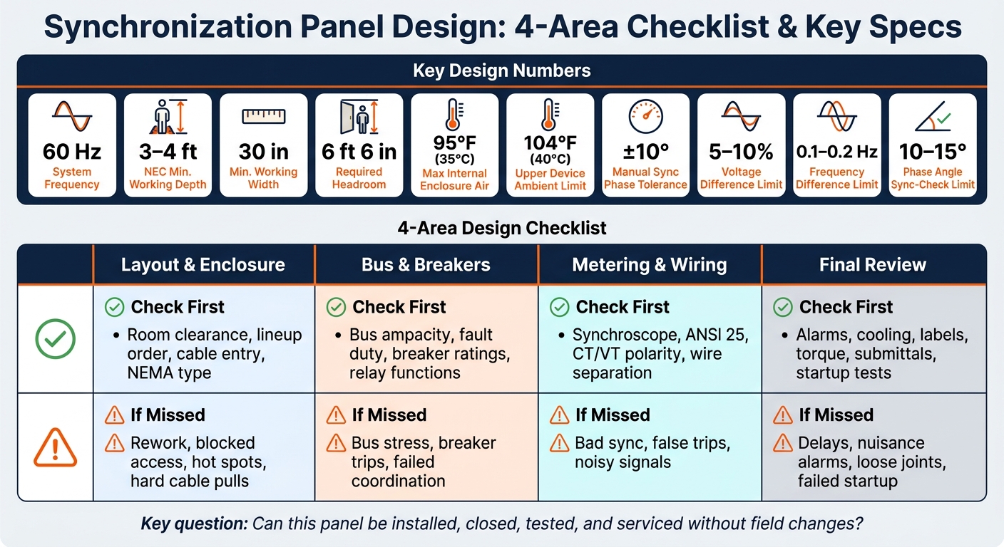
Sync Panel Design: 4-Area Checklist & Key Specs at a Glance
Quick comparison
| Design area | What I check first | What can go wrong if missed |
|---|---|---|
| Layout and enclosure | Room clearance, lineup order, cable entry, NEMA type | Rework, blocked access, hot spots, hard cable pulls |
| Bus and breakers | Bus ampacity, fault duty, breaker ratings, relay functions | Bus stress, breaker trips, failed coordination |
| Metering and wiring | Synchroscope, ANSI 25, CT/VT polarity, wire separation | Bad sync, false trips, noisy signals |
| Final review | Alarms, cooling, labels, torque, submittals, startup tests | Delays, nuisance alarms, loose joints, failed startup |
So while the topic sounds technical, the article comes down to a simple job: make sure the panel is sized right, wired right, and checked right before it ever closes in parallel.
sbb-itb-501186b
1. Panel layout and compartment checklist
Set the panel arrangement first. It affects cable routing, service access, and operator safety.
A common lineup looks like this: utility/mains → bus tie or coupler → generator incomers → synchronizing/control → outgoing feeders. If the room entry or trench routing works better in reverse, flip it. The main goal is simple: keep CT wiring, voltage references, and control cables short, and keep control and metering away from the high-energy breaker compartments.
Emergency feeders need their own vertical sections or enclosures. They should not share space with legally required or optional standby circuits. Legally required and optional standby loads should only be grouped where code allows it. That split matters during a fault, because it determines which loads stay on and which do not.
Define sections, access clearances, and enclosure rating
Use NEC 110.26 as your minimum working-space baseline: 3 to 4 ft front depth, 30 in minimum width or the width of the equipment, and 6 ft 6 in headroom. Doors and hinged panels should open 90° without hitting anything.
In practice, it helps to leave 4–5 ft front aisles for maintenance, test carts, and temporary barriers. Also leave at least one full section width at one end of the lineup for future expansion. In most cases, that means 24–36 in.
Enclosure choice depends on the room and the weather:
- NEMA 1: clean, dry indoor electrical rooms
- NEMA 3R: outdoor locations exposed to rain or sleet
- NEMA 12: indoor industrial areas with circulating dust, lint, or dripping non-corrosive liquids
For outdoor lineups in hot climates, call for internal heaters and sunshades to help control condensation and overheating. Then verify the enclosure rating on the shop drawings during submittal review.
Next, lock in cable entry. This is one of those choices that seems small until the field crew has to work around it. Top vs. bottom entry should match the building’s routing plan from the start.
Floor trenches and slab-embedded conduits usually point to bottom entry. Overhead cable tray or bus duct usually points to top entry. Bottom entry often helps with bend radius for large conductors and cuts down vertical congestion inside the sections. Coordinate this early with the electrical contractor, then put it in the equipment schedule and shop drawings so nobody ends up changing barriers or bus supports later.
Common bus vs. split bus with tie breaker
Once layout and access are set, choose the bus arrangement. That decision drives section count, breaker count, and interlocks.
| Factor | Common Bus | Split Bus with Tie Breaker |
|---|---|---|
| Reliability | Single bus fault affects all loads | One bus segment stays energized while the other is isolated |
| Fault isolation | Limited; all sources and loads are on one bus | Strong; the tie breaker separates bus sections during faults |
| Floor space | Smaller footprint, fewer sections | Larger footprint; additional tie breaker section(s) required |
| Controls complexity | Simpler interlocks and protection settings | More complex; tie breaker interlocks and synchronizing logic between bus sections |
| Installed cost | Lower initial equipment and labor cost | Higher; additional sections, breakers, and coordination studies |
| Best fit | Smaller commercial or light industrial projects | Hospitals, data centers, and mission-critical facilities requiring redundancy |
For critical facilities, a split bus with tie breaker gives you more fault isolation and lets multiple generators pick up different load groups in stages. That can make a big difference when uptime is the whole game.
For smaller commercial jobs, a common bus is often the cleaner choice. It uses less floor space, needs fewer sections, and usually costs less to install.
2. Busbars, breakers, and protection ratings checklist
Once the lineup is set, the next step is to lock in the bus, breaker, and protection ratings that carry the load and clear faults.
Size busbars for load, fault duty, and temperature rise
Size busbars based on system voltage, source count, continuous bus current, and available fault current. Before fabrication starts, check both values against the short-circuit study.
Also confirm the ambient temperature, enclosure rating, ventilation, and support spacing. Those details affect both temperature rise and short-circuit performance. Copper is usually the go-to choice for critical generator synchronization panels because it offers strong conductivity and handles heat well. Aluminum can work when cost matters more and fault levels are moderate, but it needs careful joint design and plating to help prevent corrosion at copper lugs or cable terminals. Tin plating is the common default. Silver plating is often used for main bus joints and generator incomer stabs, where low contact resistance matters most.
Make sure bus support spacing matches the manufacturer's tested fault-duty setup.
If the loads are heavy in harmonics, specify a 200% neutral bus and a continuously bonded ground bus across all sections.
| Busbar Application | Typical Continuous Rating (A) | Material | Plating | Short-Circuit Withstand (kA, 3 cycles) |
|---|---|---|---|---|
| Small sync panel bus | 1,600–2,500 | Copper or Aluminum | Tin-plated | 35–50 |
| Medium sync panel bus | 2,500–4,000 | Copper | Tin-plated | 50–65 |
| Large sync panel bus | 4,000–6,000 | Copper | Tin or Silver-plated | 65–85 |
| Neutral bus (harmonic duty) | 200% of phase rating | Copper | Tin-plated | Same as phase bus |
| Ground bus | 50–100% of phase rating | Copper | Bare or Tin-plated | Ground-fault duty as per study |
Verify the final values against the short-circuit and coordination study.
Next comes the breaker choice and trip functions that fit that bus duty.
Select ACBs, MCCBs, and relay functions for synchronization duty
Use ACBs for generator incomers and bus ties. Use MCCBs for outgoing feeders.
| Panel Section | Preferred Breaker Type | Typical Rating Range (A) | Key Reason |
|---|---|---|---|
| Generator incomer | ACB | 800–6,300 | High fault duty, sync-check interface, generator duty rating |
| Bus coupler / tie | ACB | 1,600–6,300 | Fault isolation, interlock logic, short-time withstand |
| Outgoing feeders | MCCB | 100–3,200 | Cost, space, adequate for branch-level fault duty |
During submittal review, check the voltage class, frame size and continuous current rating, interrupting rating, and close/trip coil control voltage for each breaker. The interrupting rating has to meet or exceed the available fault current at that breaker location. The voltage class should also match the system, such as a 600 V class breaker on a 480 V system. And one more thing: make sure the breaker is listed for generator duty.
Use one multifunction relay for each generator incomer. It usually covers 25 sync-check, 27/59 under/overvoltage, 81 over/under frequency, 32 reverse power, 40 loss of field, and 50/51 overcurrent. Wire relay outputs to trip, close-permissive, and alarms. Then coordinate the settings with the short-circuit and coordination study so selectivity stays in place.
If you're dealing with used equipment, inspect the bus plating, joint condition, and support bracing for signs of prior fault stress before acceptance.
After bus, breaker, and protection ratings are set, move to meter placement and control wiring.
3. Metering, relays, and control wiring checklist
With bus and breaker ratings set, the next step is operator metering, relays, and control wiring.
Place meters, synchroscope, and relays for operator use
Start with the operator’s view: what they can see, what the relays are watching, and how the wiring gets there.
Each generator should include, at minimum, metering for voltage (line-to-line), current (per phase), frequency (Hz), real power (kW), reactive power (kVAR), and power factor (PF). You also need bus voltage, bus frequency, and total bus kW/kVAR for preclose checks.
Mount the synchroscope at eye level, usually 5–6 ft above finished floor. During manual synchronizing, the pointer should move toward 12 o'clock at close. For low-voltage applications, a tolerance of about ±10° is typical.
Wire ANSI 25 in series with the breaker close circuit for both manual and automatic sync. Typical settings limit:
- Voltage difference to 5–10%
- Frequency difference to 0.1–0.2 Hz
- Phase angle to 10–15°
For automatic sync, verify that the controller uses the right VT sources and close permissives. The synchroscope and sync-check relay should use the correct VT sources too: one from the generator side and one from the bus side. Add accessible test points so commissioning teams can check VT polarity without disturbing permanent wiring.
Protection relays and load-sharing controllers should be grouped by generator set. Use engraved or lamacoid nameplates, and keep device IDs in exact match with the one-line and elementary schematics. Place terminal blocks and test switches in lower or rear compartments where people can reach them without a struggle. Drawout test blocks for CT/VT circuits make it easier to inject test signals and verify protection without pulling wiring apart.
Document all AVR and governor signals in an I/O list tied to terminal numbers and PLC tags. That sounds basic, but it saves a lot of grief. Signal-type mismatches - like 4–20 mA versus 0–10 V governor inputs - are a common reason commissioning gets held up.
Separate control wiring, interlocks, and terminal identification
Once device placement is set, lock in separate routing zones for power, control, signal, and communications. That separation helps cut noise and avoid misoperation.
| Circuit Type | Routing | Min. Separation from Power Cables | Shielding |
|---|---|---|---|
| Power (bus, feeders, breaker stabs) | Dedicated bus compartment or power tray | - | None required |
| Control (breaker coils, interlocks, status contacts) | Separate control duct or tray | 2–3 in (50–75 mm) from power conductors where possible; barrier preferred | None required |
| Signal/Analog (4–20 mA, PT/CT secondary wiring, AVR/governor references) | Dedicated signal tray or conduit | 8–12 in (200–300 mm) from power cables | Shielded twisted pair; shield grounded at one end only |
| Communication (Ethernet, RS-485, Modbus, CANbus) | Communication-specific raceway away from high-EMI sources | Keep separate from power wiring and follow manufacturer recommendations | Labeled at every entry and exit point |
After routing, standardize wire IDs and color coding so checkout moves faster. Use NEC/NFPA wire-color conventions. Use red for 120 V AC control, blue for DC control, orange for always-live circuits, and yellow for externally energized interlocks. Keep white, gray, green, and green/yellow for grounded conductors and equipment grounds.
Every conductor should have its own wire number at both ends. The marking should read from the service side and sit close enough to the termination to be seen without moving the wire. The numbering also needs to match the schematics exactly.
Small wiring errors can cause big headaches. Incorrect CT polarity is a leading cause of wiring-related protection misoperations, and bad wiring often leads to early relay trips. Before energization, perform point-to-point checks on all sync AC circuits and breaker-close DC paths.
4. Alarms, cooling, sourcing review, and final installation checks
Check alarms, annunciation, and panel cooling
With the wiring done, the last step before energization is to check alarms, cooling, and startup paperwork.
Your alarm scheme should cover sync failure, breaker failure to open or close, reverse power, overcurrent, ground fault, and over/under voltage and frequency. Split alarms into three tiers - trip-critical, operational, and informational - so operators can tell the difference between a minor nuisance and a protection event at a glance. Each protection function needs to be tied to the right tier.
Annunciation needs to be defined during design, not at the last minute. For local indication, use a dedicated annunciator window or a mimic panel with grouped alarm lights and plain color coding: red for trips, amber for warnings, and green for normal. For remote indication, provide Form C dry contacts for key conditions and SCADA outputs such as Modbus TCP or IEC 61850.
Cooling matters more than people think. Keep enclosure air below 95°F (35°C), and treat 104°F (40°C) as the upper limit for installed devices. Put louvers low for intake and high for exhaust so air moves the way it should. Filters should be easy to clean or replace without removing live components, and fan access should still leave the required working space. In critical facilities, specify redundant fans and a high-temperature alarm at 104°F (40°C).
Final checklist: submittals, receiving inspection, and startup readiness
Next, lock down the submittals and inspect the equipment before it goes in place.
Before shipment, confirm the approved submittals, including:
- Drawings
- Relay settings
- Breaker curves
- Bus data
- Torque values
- CT/PT data
- Spares
Relay settings should be provided in both human-readable tables and native software formats so the commissioning team can load them straight in.
When the equipment arrives, inspect the enclosure for dents, gasket damage, and door alignment. Then check every breaker, relay, meter, and terminal block against the approved bill of materials. Make sure nameplates and labels match the drawing references, and verify UL/NRTL markings against the purchase order. Mislabeled gear is the kind of problem that seems small until it holds up startup. If replacement parts are needed after receiving, use Electrical Trader to source them, then verify ratings, certifications, and compatibility before installation.
Before energization, confirm cable bending radius and landing space. Apply the manufacturer’s specified torque values to all bus joints and lugs with a calibrated torque tool. Then test every interlock in the final operating sequence, simulate each alarm with a relay test set, verify HMI, LED, dry-contact, and network responses, and log the results with timestamps. An infrared scan of busbars and terminations under load can help catch poor connections or ventilation gaps before they turn into failures.
FAQs
When do I need a split-bus sync panel?
You need a split-bus synchronization panel when the system has to keep power sources isolated, so multiple generators can't energize the same bus at the same time.
That setup matters for dead-bus arbitration logic. It helps make sure only one generator connects to an unpowered bus at a time. It also cuts down single points of failure and improves safety during parallel operation.
How do I verify breaker and bus fault ratings?
Calculate the maximum available fault current at the installation point. To do that, look at the system impedance, how close the transformer is, the cable length, and any fault current contribution from motors.
Then compare that number with the equipment nameplate ratings. The breaker interrupting capacity and the panel SCCR must be equal to or higher than the available fault current.
One detail trips people up all the time: the overall SCCR is capped by the weakest component. So don’t stop at the main pieces. Check every device, and review the manufacturer datasheets and NEC labeling before you sign off on the installation.
What should I test before first energization?
Before first energization, make sure the system is safe, intact, and set up the way the design calls for. This is the moment to slow down and check the basics, because small mistakes here can turn into big problems once power is on.
Check wiring against the schematics, confirm terminal torque values, perform insulation resistance testing, and verify grounding and bonding.
Then move to controls and protection. Confirm I/O and binary signal mapping, review relay settings and protection logic, verify communication links, and test safety-critical circuits and alarm annunciation.





