Ultimate Guide to Generator Synchronization
Generator synchronization is the process of aligning a generator's electrical characteristics with the power grid before connection. This ensures the generator operates in harmony with the grid, preventing equipment damage and maintaining system stability.
To synchronize a generator, four key parameters must match:
- Voltage magnitude: Align the generator's voltage with the grid's.
- Frequency: Match the generator's frequency to the grid's (e.g., 60 Hz).
- Phase angle: Ensure the phase angle is zero at the moment of connection.
- Phase sequence: Confirm the generator's phase rotation matches the grid's.
Tools like synchroscopes, synchronization lamps, and modern digital systems help monitor and align these parameters. Proper synchronization avoids issues like inrush currents, mechanical stress, and reactive power imbalances. While manual methods work, automated systems offer precision and reduce risks.
Key takeaway: Synchronization is vital for safe generator operation and grid stability.
Generator Synchronization (Full Lecture)
sbb-itb-501186b
Required Conditions for Synchronization
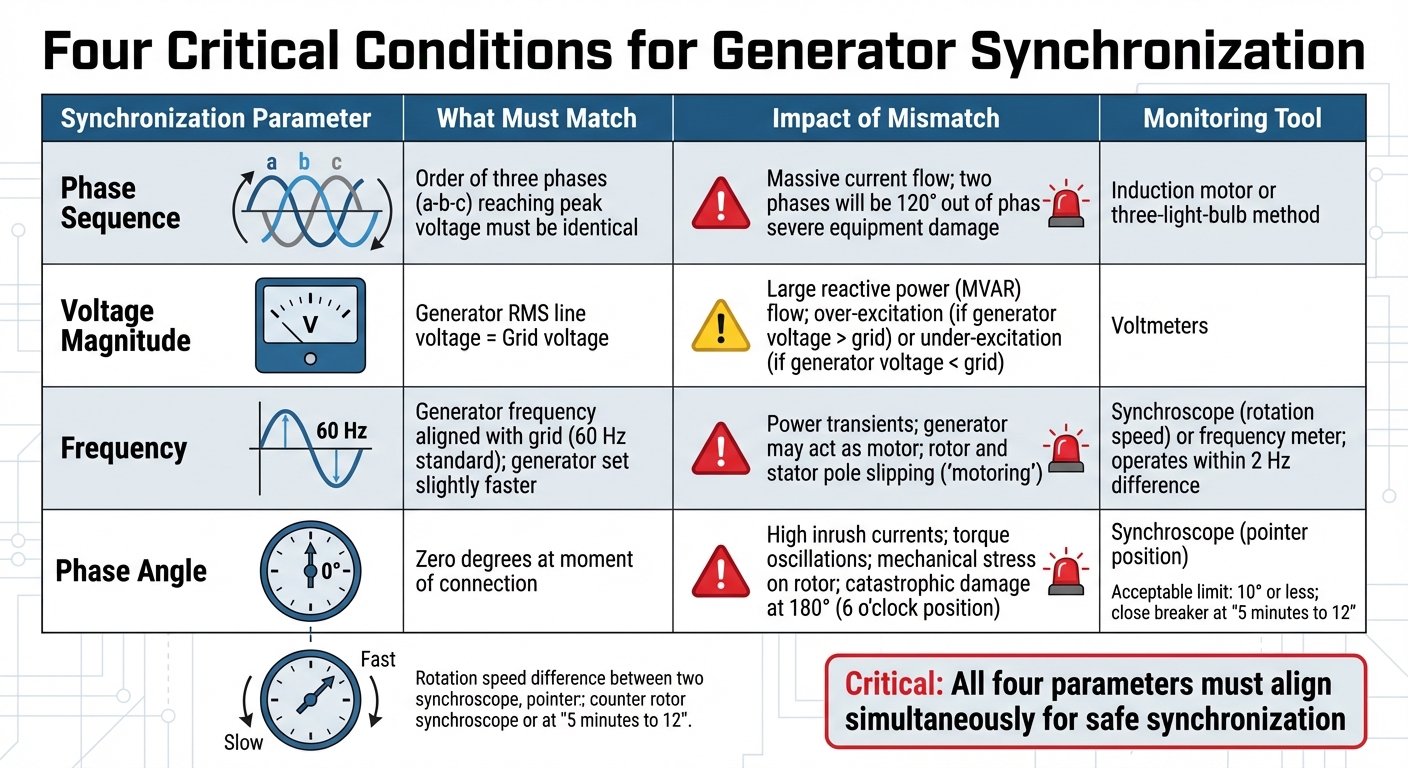
Four Critical Generator Synchronization Parameters and Their Effects
To safely connect a generator to the grid, several precise conditions must be met. These include aligning the phase sequence, voltage magnitude, frequency, and phase angle between the generator and the grid. A single mismatch in any of these can lead to equipment damage, so careful attention is crucial.
Phase Sequence Matching
Phase sequence refers to the order in which the three phases (a-b-c) reach their peak voltage. The generator's phase rotation must match the grid's exactly. If the sequences don’t align, two of the three phases will be 120° out of phase, even if the first phase appears correct. This mismatch leads to massive currents that can severely damage equipment.
Phase sequence errors usually occur during initial setup or after maintenance when power leads or potential transformer (PT) leads are accidentally swapped. To verify the phase sequence, use tools like an induction motor or the three-light-bulb method. In the latter, all three bulbs should achieve equal brightness simultaneously.
If a mismatch is detected, you can correct it by swapping any two of the three phase connections on one machine. Ensuring this alignment is critical before moving forward.
Voltage Magnitude Equality
The generator’s RMS line voltage must match the grid’s voltage before connection. Any difference can cause a significant reactive power (MVAR) flow when the breaker is closed. If the generator’s voltage exceeds the grid’s, it becomes overexcited and exports MVAR. Conversely, if the voltage is lower, the generator becomes under-excited and absorbs MVAR from the grid.
To equalize the voltages, adjust the generator’s field current using the Automatic Voltage Regulator (AVR). Voltmeters are essential for fine-tuning and ensuring a smooth reactive power balance once connected.
Frequency Alignment
The generator’s frequency must align with the grid’s standard of 60 Hz. In practice, the generator is often set to run slightly faster than the grid. This ensures the generator begins supplying power immediately, rather than drawing power and acting as a motor.
If the generator operates slower than the grid at the moment of connection, the grid will try to bring it up to speed. This can cause the rotor and stator to slip poles, a destructive phenomenon known as "motoring". Frequency adjustments are made by controlling the prime mover’s speed, which involves regulating the fuel, steam, or water flow to the engine or turbine.
A synchroscope is used to monitor frequency differences. If the needle rotates clockwise (marked "Fast"), the generator is running faster than the grid. If it rotates counter-clockwise (marked "Slow"), it’s running slower. Synchroscopes generally operate only when the frequency difference is within 2 Hz.
Phase Angle Alignment
The phase angle between the generator and grid voltages must be zero at the moment of connection. A nonzero phase angle can lead to inrush currents and mechanical stress, as the grid forces the generator into phase. This results in torque oscillations that can damage the equipment.
A synchroscope helps monitor the phase angle. Operators typically close the breaker when the synchroscope pointer is slightly before 12 o’clock (around "5 minutes to 12") and moving toward 12 o’clock. This accounts for the breaker’s closing delay and ensures smooth synchronization.
The most dangerous scenario occurs when the phase angle is 180°, indicated by the synchroscope pointing at 6 o’clock. Closing the breaker in this position can cause catastrophic mechanical and electrical stress.
The table below summarizes the effects of mismatches and the tools used to monitor each condition:
| Condition | Impact of Mismatch | Monitoring Tool |
|---|---|---|
| Phase Sequence | Massive current flow; mechanical damage | Induction motor or three-light-bulb method |
| Voltage Magnitude | Large MVAR flow; over/under-excitation | Voltmeters |
| Frequency | Power transients; generator may act as a motor | Synchroscope (rotation speed) or frequency meter |
| Phase Angle | High current inrush; torque oscillations, rotor stress | Synchroscope (pointer position) |
Synchronization Tools and Methods
Professionals rely on various generator synchronization methods, ranging from basic lamp setups to advanced digital systems. The choice depends on factors like generator size, precision needs, and budget. Here's a breakdown of the main tools and techniques used to achieve synchronization.
Synchronization Lamps
The lamp method is one of the simplest approaches to synchronization. It uses three lamps connected between the generator and the grid to visually indicate alignment. Two common variations are:
- Dark Lamp Method: Lamps are connected across matching phases (A1–A2, B1–B2, C1–C2). The breaker is closed when all lamps go dark.
- Three Bright Lamp Method: Lamps are cross-connected (A1-B2, B1-C2, C1-A2), and the breaker is closed when all lamps reach full brightness simultaneously.
While straightforward, this method has limitations. Lamps can appear dark even with a significant phase difference, as they dim at around 50% of their rated voltage. This makes it less accurate and better suited for low-power setups. If the lamps fail to glow and dim together, it indicates an incorrect phase sequence, requiring two leads to be swapped.
Using a Synchroscope
A synchroscope offers a more precise alternative by providing real-time feedback on the phase angle and frequency difference. Its rotating needle moves:
- Clockwise when the generator runs faster than the grid (marked "Fast").
- Counter-clockwise when the generator runs slower (marked "Slow").
The needle points to the 12 o'clock position when there is zero phase difference, signaling the optimal time to close the breaker.
Although more accurate than lamps, this method still depends on the operator's judgment. It doesn't account for breaker lag automatically, so using a sync-check relay (Device 25) alongside the control switch is essential to prevent out-of-phase closures caused by human error.
Digital Synchronization Systems
For maximum precision, digital synchronizers are the go-to solution. These systems automate the process, using advanced logic to adjust speed and voltage. They calculate the exact moment to close the breaker, factoring in real-time slip data and the mechanical closing time to ensure contact occurs at zero degrees.
Modern digital synchronizers can handle slip frequencies as low as 0.0001 Hz, equivalent to one synchroscope revolution every 2.8 hours. They also include "dead bus logic", which allows the generator to connect to a de-energized bus without waiting for synchronization parameters - essential for black-start scenarios. While these systems involve higher initial costs, they are now the standard for large power stations and complex facilities where precision and reduced operator workload are critical.
How to Synchronize a Generator: Step-by-Step
Synchronizing a generator involves a precise process that ensures the generator aligns with the grid's parameters. It requires careful preparation, adjustments, and timing to avoid potential damage or inefficiencies. Here's a breakdown of how professionals handle this task.
Preparing the Generator
Start by confirming the phase sequence alignment. Use standard methods to verify the phase sequence, as mismatched sequences can lead to damaging inrush currents when the generator connects to the grid. If the sequences are out of order, swap any two phase leads to correct them.
Next, test the synchroscope before proceeding. Ensure the generator speed allows the synchroscope to display both "Slow" and "Fast" rotations. This step ensures you’re not relying on defective instruments during synchronization. Remember, synchroscopes only rotate when the frequency difference is 2 Hz or less.
Adjusting Frequency and Voltage
Once the phase sequence is aligned, move on to fine-tuning the generator’s voltage and frequency. Adjust the voltage using the excitation system, and slightly increase the generator's frequency above the grid’s frequency using the prime mover. This step is crucial because closing the breaker with a voltage mismatch can cause a significant flow of reactive power (MVAR), even if the phase and frequency align.
| Parameter | Control Mechanism | Monitoring Tool | Synchronization Goal |
|---|---|---|---|
| Voltage Magnitude | Field Current / Excitation System | Voltmeter | Match grid voltage |
| Frequency | Prime Mover / Governor Speed | Frequency Meter / Synchroscope | Slightly higher than grid |
| Phase Angle | Timing of Breaker Closure | Synchroscope | Zero degrees (12 o'clock) |
Monitoring and Closing the Breaker
With voltage and frequency adjusted, the final step is aligning the phase angle. Watch the synchroscope needle as it moves clockwise toward the 12 o'clock position, which signals zero phase difference. For manual synchronization, close the breaker when the needle approaches the 5-minute mark on the clock face during its clockwise rotation. This timing ensures the breaker closes at the optimal phase angle.
Manufacturers often specify an angular limit of 10° or less and a slip frequency of less than 0.067 Hz for synchronization. At this slip rate, the synchroscope completes a full rotation roughly every 15 seconds. For added safety, use a sync-check relay (Device 25) in series with the control switch during manual operations. This prevents accidental breaker closure if the generator is out of phase. Properly timing the breaker closure ensures smooth integration with the grid and avoids disruptions.
After Synchronization: Operations and Troubleshooting
After synchronization, maintaining stability in the grid depends on effective load management and quick troubleshooting.
Load Sharing and Control
Once the generator is connected to the grid, the grid acts as an infinite bus, meaning that voltage and frequency remain constant. At this stage, you can no longer directly control these parameters. Instead, governor set points manage real power (measured in MW), while field current adjustments control reactive power (measured in MVAR). For instance:
- Increase the governor speed set point to raise real power output.
- Adjust the field current to manage reactive power - raising it exports MVAR, while lowering it absorbs MVAR from the grid.
"When the generator is coupled to an infinite bus, its frequency and voltage remain constant; thus, the governor set points and field current control the real and reactive power output from the generator." - Edvard Csanyi, Founder, Electrical Engineering Portal
Modern systems often use automatic synchronizing panels or digital controllers to make these adjustments in real time, reducing the chance of operator error. However, always monitor the generator's thermal limits. Heat in the armature windings determines the total kVA capacity, while field winding heat limits the internal voltage that can be generated.
Now, let’s look at some common problems that can arise when parameters are slightly off.
Common Synchronization Problems
Voltage mismatches can lead to sudden reactive power surges. To avoid this, ensure voltage differences are kept below 5%, as larger differences can cause excessive shaft torque and stress on equipment.
Frequency mismatches are even more dangerous. If the generator's speed is slower than the grid's when the breaker closes, the grid forces the generator to accelerate, making it act like a motor. This "slipping poles" condition can result in severe mechanical damage to both the rotor and stator. Similarly, phase angle errors - even with matched frequencies - can cause inrush currents and mechanical stress. These examples highlight how improper synchronization can lead to significant risks.
Protection Against Out-of-Sync Faults
To address these challenges, robust protective systems are critical. ANSI 25 sync-check relays are commonly used to oversee both manual and automatic synchronization, preventing breaker closure if angular differences, voltage mismatches, or frequency deviations exceed safe limits. For added reliability, these relays should be installed separately from automatic synchronizing relays to prevent single points of failure.
"One of the easiest way to damage a generator is to synchronize or parallel out of phase with the electrical system. Out-of-phase synchronizing operations can damage or reduce the remaining life of generator rotors and stationary components." - Edvard Csanyi, Electrical Engineer and Founder of EEP
Real-world examples emphasize the importance of these precautions. For instance, in July 2020, at a coal-fired power plant, a generator was synchronized to a 500 kV system with a 12-degree angular difference. This caused a torque spike of 1.5 per unit (150% of full load), shaking the turbine deck violently and illustrating the physical toll of even minor out-of-sync events.
To prevent such incidents, relay settings should allow a 5° advance and 5° lag, keeping the total phase angle within a 10° limit. Modern digital relays can also detect slow breaker closures and activate breaker failure relays if the phase angle drifts beyond safe thresholds before the contacts close.
Conclusion
Generator synchronization hinges on aligning four critical parameters: phase sequence, voltage magnitude, frequency, and a zero-degree phase angle. A mistake in any of these can lead to costly equipment damage, operational downtime, and serious safety hazards.
To address these challenges, the industry has increasingly embraced automated synchronization systems. Modern generators demand far greater precision than older models, and human error remains a major risk factor. As Edvard Csanyi, Founder of EEP, explains:
"Electrical and mechanical systems have become less tolerant of the rough synchronization as generator sizes have grown and designs have become more efficient".
While synchroscopes and manual methods still play a backup role, automation should be the go-to solution for most scenarios.
Additionally, sync-check relays (Device 25) are essential for preventing breaker closures when synchronization parameters fall outside safe thresholds - typically within a 10° phase angle. These relays act as a last line of defense, protecting equipment from the catastrophic effects of out-of-phase closures. Under no circumstances should these systems be bypassed, even during testing.
For manual synchronization, the "5 minutes to 12" rule offers a useful guideline. This method ensures the generator starts exporting power immediately instead of drawing from the grid. Modern digital synchronizers, capable of handling slip frequencies as low as 0.0001 Hz, underscore the level of precision required in today’s systems.
Whether you're commissioning new equipment or maintaining older setups, prioritize safety by adhering to proper training, regular equipment checks, and strict compliance with manufacturer guidelines. Synchronization errors can have serious consequences, but following these best practices helps ensure grid stability and operational safety.
FAQs
What happens if I close the breaker while the generator is out of phase?
Closing the breaker while the generator is out of phase can lead to major problems. These include power surges, equipment damage, and even the tripping of the generator or connected systems. To prevent such risks, it's crucial to ensure the generator is properly synchronized before closing the breaker.
Why should a generator run slightly faster than the grid before syncing?
When preparing to synchronize a generator with the grid, running it slightly faster than the grid plays a crucial role. This small speed difference helps align key parameters such as frequency and voltage effectively. By allowing for gradual adjustments, it minimizes sudden changes (transients) and mitigates the risk of damage or instability during the connection. This approach ensures a smoother and safer synchronization process.
When should I use a sync-check relay (ANSI 25) versus a digital synchronizer?
A sync-check relay (ANSI 25) is a protective device that verifies whether voltage, frequency, and phase angle are within acceptable limits before allowing a breaker to close. This is especially useful during manual or semi-automatic synchronization processes to ensure safe operation.
On the other hand, a digital synchronizer takes automation to the next level. It manages the entire synchronization process by automatically adjusting generator parameters and closing the breaker at the perfect moment when conditions align.
In practice, the sync-check relay serves as a safety measure to confirm proper conditions, while the digital synchronizer provides fully automated and precise control, making it ideal for more complex systems.