




SVC Sizing and Location for Power Systems
If I had to boil this down to one line, it’s this: an SVC should be sized from measured system data, placed at the bus that gives the best voltage and loss results, and checked for harmonics, fault duty, and site fit before anyone buys equipment.
I’d focus on three decisions first:
- How many MVAr are needed
- Which bus or substation should get the SVC
- Whether harmonics, short-circuit duty, controls, and site limits allow that plan
The article makes a few points clear:
- I should use 7 to 14 days of logged data, plus 1- to 5-second disturbance data, before setting the rating.
- I should hold voltage near 0.95–1.05 pu in normal conditions and check lower post-fault limits like 0.90–0.95 pu for short periods.
- I should expect dynamic duty to be 20% to 50% above continuous duty in some cases.
- I should compare buses by voltage support, MW loss reduction, and stability margin, then reject any bus that breaks fault-duty limits.
- I should run harmonic studies against IEEE 519, with 5% THD often used as a top voltage limit below 69 kV at the PCC.
Here’s the short version of how I’d read the piece:
| Decision | What I’d check first | What can block approval |
|---|---|---|
| Sizing | Load logs, voltage limits, motor starts, flicker, contingencies | Too little MVAr range or no headroom |
| Location | Power flow, weak-bus results, loss savings, stability gain | Breaker or relay fault-duty limits |
| Final design | Harmonics, resonance, filter needs, space, control coordination | IEEE 519 issues, no site space, control clashes |
Put simply: the right SVC is not just the one with enough reactive power on paper. It also has to work during peak load, light load, faults, and switching events - while still fitting the yard and playing well with capacitor banks, filters, relays, and OLTC controls.
If I were using this article to make a decision, I’d treat it as a pre-procurement check list: size from field data, rank buses from study results, then clear harmonics, short-circuit, and layout checks before release.
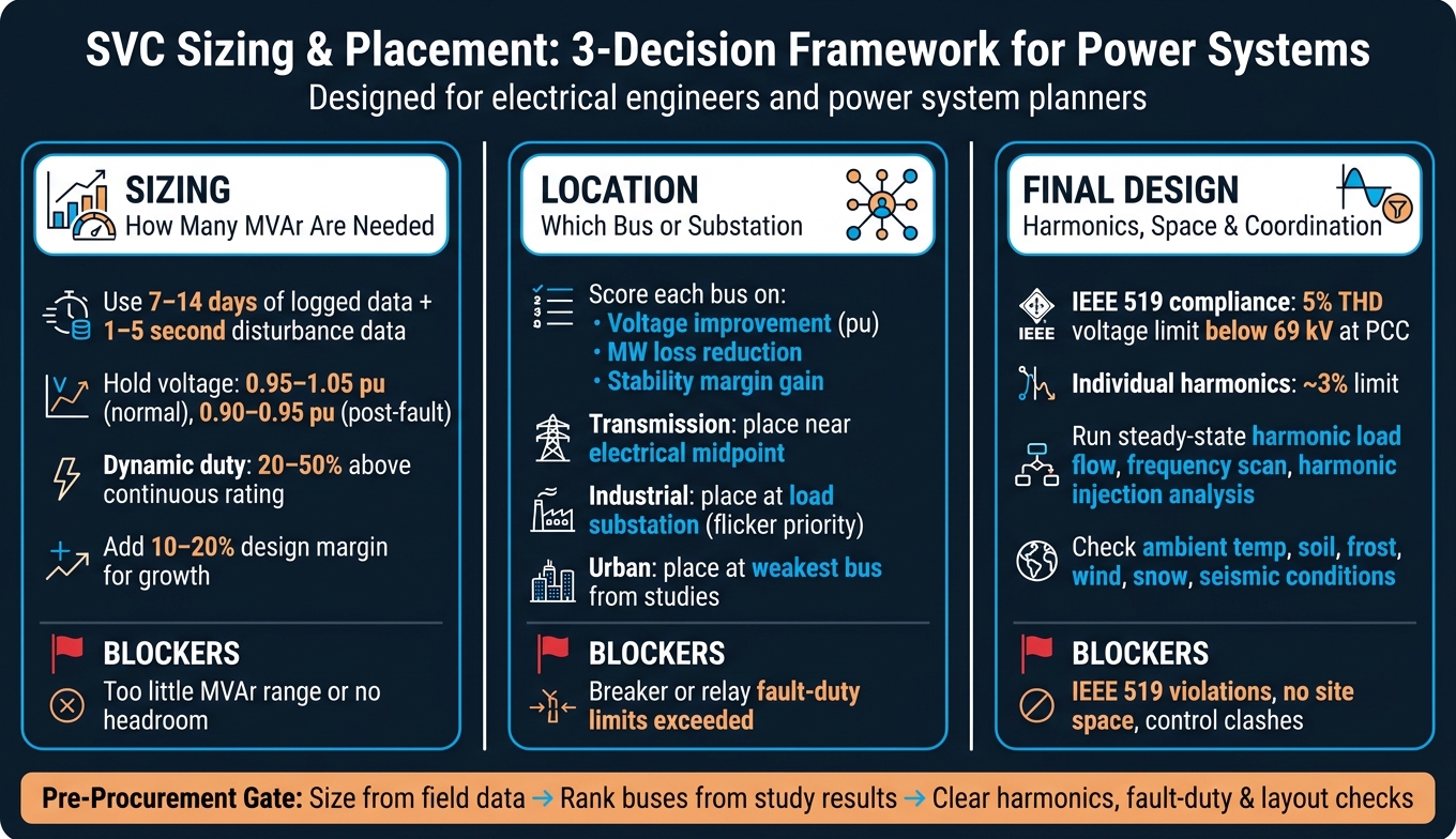
SVC Sizing & Placement: 3-Decision Framework for Power Systems
Dynamic VAR Compensation: Static VAR Compensators - or SVCs
sbb-itb-501186b
Checklist 1: Size the SVC Based on Load Profile and Voltage Requirements
Set the MVAr rating from measured load data, voltage limits, and dynamic duty - not rough guesses. The right size depends on the job the SVC is doing, whether that’s transmission support, industrial voltage control, or power factor correction. This checklist shows what data to collect, which voltage limits to use, and why dynamic duty can push the rating above what steady-state math suggests.
Review Interval Load Data Before Setting the MVAr Rating
Start with 1- to 5-minute logs of voltage, current, kW, kVAR, power factor, and THD over 7 to 14 days. Then add 1- to 5-second logs around known disturbances. That gives you a fuller picture of how the system behaves, not just how it looks on a calm day.
Use that data to spot:
- Peak lagging kVAR
- Light-load leading kVAR
- Motor starts
- Cyclic load swings
- Voltage-weak periods
This is also where you’ll catch motor-start spikes and repeating swing patterns from cyclical loads. In plain terms, the load profile tells you where the bus is most likely to struggle.
Size the SVC for the worst-case duty cycle, then add a 10–20% design margin for load growth and model uncertainty.
Set Bus Voltage Limits and Study Normal and Contingency Cases
Use 0.95–1.05 pu for normal operation and 0.90–0.95 pu for limited post-contingency operation, and only for limited duration, in line with ANSI C84.1 planning practice.
Build load flow cases for at least these three scenarios:
- Peak load: Keep voltage within 0.95–1.05 pu by supplying enough lagging MVAr to avoid undervoltage.
- Light load: Keep voltage within 0.95–1.05 pu by absorbing leading MVAr to avoid overvoltage.
- N-1 contingency: Stay within 0.90–0.95 pu for limited duration only, and check both thermal and voltage limits across the full reactive range.
A bus can look fine at peak load and still run into trouble during light-load hours. That’s why both ends of the operating range matter.
Check Dynamic Support Needs
Dynamic ratings often run 20% to 50% above continuous ratings. That gap matters. A unit that looks large enough on paper may still fall short during a motor start, after a fault, or under flicker duty.
Run time-domain studies for:
- Motor starts
- Fault recovery
- Flicker conditions
If dynamic duty is above steady-state demand, specify separate continuous and short-term MVAr ratings.
Once the MVAr rating is set, compare candidate buses using power flow and voltage-stability results.
Checklist 2: Select the Right Bus or Substation Location
Once the MVAr rating is set, the next step is simple in theory but tricky in practice: pick the bus that gives you the most system value. You’re looking for the best mix of voltage support, lower losses, and better stability, without running into fault-duty limits.
Compare Candidate Buses Using Power Flow and Voltage Stability Results
Run base-case and contingency power flows for each candidate bus under peak, light, and N-1 conditions. Then rank the buses with a voltage-stability index such as L-index.
For each bus, score three things:
- Voltage improvement: change in minimum bus voltage in per unit
- Real power loss reduction: MW saved
- Voltage stability margin improvement: how much stability headroom improves
That gives you a practical ranking instead of a gut-feel choice. In plain English, the best bus isn’t just the one that bumps voltage the most. It should also cut losses and help the system stay on its feet when conditions get rough.
Use the top-ranked bus as the starting point for fault-duty checks.
Check Short-Circuit Level and Bus Strength
Run three-phase and single-line-to-ground fault studies at each candidate bus with the updated network model, including the proposed SVC transformer connection. Then compare the fault current results with:
- existing breaker interrupting ratings
- CT and relay limits
- the SVC equipment’s short-circuit withstand ratings
Bus strength matters a lot here. A weak bus can make the SVC more effective from a voltage-support standpoint, but it can also make control harder. A strong bus tends to be easier to control, yet the voltage gain may be less obvious.
And there’s a hard stop to watch for: high fault duty can knock a bus out of the running right away. If fault current goes past the rating of existing equipment, you’ll need station upgrades or you’ll have to move on to the next candidate.
If fault duty checks out, move on to space, harmonics, and coordination.
Match the Location to the Application Type
The use case should drive the siting rule. Different applications care about different outcomes, so the ranking metric that matters most will change.
- Transmission: Put the SVC near the electrical midpoint, where voltage stability gain is usually highest.
- Industrial loads: Put it at the load substation to control flicker, with flicker response taking priority over the other metrics.
- Urban load centers: Put it on the weakest bus found in studies or operating data, where voltage support has the biggest payoff.
After you pick the bus, check harmonics, space, and equipment coordination before procurement.
Next, verify harmonics, site constraints, and equipment coordination.
Checklist 3: Verify Harmonics, Space Constraints, and Equipment Coordination
After the bus is selected, check distortion, footprint, and coordination before you lock in the design.
Run Harmonic and Resonance Studies Early in the Project
Run harmonic studies before finalizing filter design.
Start with the core studies:
- Steady-state harmonic load flow to measure voltage THD and individual harmonic distortion at the point of common coupling (PCC) across different SVC operating modes
- Frequency scan (impedance vs. frequency) to find parallel and series resonance points with existing capacitor banks and filters connected
- Harmonic injection analysis covering major nonlinear loads such as drives, rectifiers, arc furnaces, or HVDC links
Then compare the results with IEEE 519 limits. For systems below 69 kV, total voltage THD at the PCC is usually limited to 5%, with individual harmonic components often around 3%, depending on voltage level. Current distortion limits depend on the short-circuit-current-to-load-current ratio at the PCC, which means weaker buses face tighter limits.
Don’t stop at the base case. Run light-load, peak-load, and contingency cases too. The goal is simple: make sure the SVC and its filters stay within IEEE 519 limits in every credible operating condition.
Once the electrical side checks out, move to the site itself.
Confirm Available Space, Clearances, and Site Conditions
Make sure the SVC footprint, electrical clearances, access routes, and local site conditions fit the substation layout before detailed design starts.
Check the SVC footprint against site boundaries, nearby equipment, and access restrictions. For outdoor, air-insulated SVC yards, electrical clearances should follow IEEE 1427.
Site conditions can change the design more than people expect. Review:
- Ambient temperature ranges in °F
- Soil bearing capacity
- Frost depth
- Wind and snow loading
- Seismic requirements under local codes
Climate and site exposure matter as well. In cold areas, outdoor control cabinets may need space heaters. In hot locations, capacitors and reactors may need derating or added ventilation. Sites with dust, chemicals, or heavy vibration may call for NEMA 3R, 4, or 4X enclosures, filtered ventilation, or HVAC.
Coordinate With Existing Capacitor Banks, Filters, Protection, and Controls
List every reactive device already in service: fixed capacitors, switched banks, existing harmonic filters, and on-load tap changers. Include their control logic and normal switching patterns. Then simulate how they operate together.
The control approach should give the SVC priority for fast response while limiting automatic capacitor switching when the SVC is active. Capacitors provide slower bulk reactive support. The SVC handles fast dynamic regulation. Deadbands, time delays, and blocking signals help prevent the two from hunting or oscillating.
Also check that capacitor switching, filter protection, and SVC control logic don’t clash during normal operation or faults.
Document each existing device, relay setting, and control block before final procurement.
Conclusion: Final SVC Sizing and Placement Checks Before Procurement
Use the three checklists above as the last gate before procurement. Then do one more pass using field data and study results that have already been checked.
- Load profile validation: Compare SCADA data with the load model. If peak demand, minimum demand, power factor, or seasonal swing differs by more than 5% to 10%, revise the MVAr rating before procurement.
- Voltage and reactive range confirmation: Studies should show that the SVC can hold bus voltage inside the target band during peak load, light load, and credible contingencies, while keeping 10% to 20% reactive headroom for growth.
- Bus selection finalization: Lock in the bus selection with written technical justification. Then recheck fault levels, breaker ratings, transformer through-fault limits, and protection coordination. If there is any fault-duty or coordination issue, that bus is out. Record all relay-setting and transformer-impedance changes in the procurement package.
When all of these checks pass, release the SVC package for procurement.
FAQs
How do I know if my system needs dynamic or continuous MVAr sizing?
Review your load profile and power quality.
You’ll usually need dynamic or continuous MVAr sizing when your system has fast-changing loads. That includes equipment like arc furnaces, large motors, welding equipment, or elevators. These loads can trigger voltage dips or load swings faster than standard stepped capacitor banks can respond.
It also makes sense to look at this approach when THD exceeds 5% or when you need real-time, millisecond-level reactive power control to keep the system stable and avoid overcorrection or resonance.
What makes one bus a better SVC location than another?
The best bus for a Static VAR Compensator (SVC) is usually the one closest to the main inductive or fast-changing loads that are causing flicker, voltage sags, or phase imbalances.
Why put it there? Because the SVC can support reactive power right where the problem starts. That usually helps improve voltage control and cut line losses.
The bus should also fit the system’s short-circuit level and harmonic profile. On top of that, the site needs enough room for cooling and maintenance.
When should harmonic and fault-duty studies be done?
Do harmonic and fault-duty studies during the initial design phase for new facilities or expansions, before ordering equipment.
Run them again any time new power sources or loads - like solar, storage, generators, or EV charging - change the system setup. Harmonic review should happen early so you can check total harmonic distortion and see whether filtering is needed for IEEE 519. Fault-duty review makes sure equipment ratings match the available short-circuit levels.





