




Safe Isolation Procedure for Electrical Panels
If I open a panel before I lock out every power source and test for zero voltage, I am taking a live-work risk. In the U.S., electrical exposure causes about 150 deaths per year, and many lockout/tagout failures happen because power was not fully shut off first.
Here’s the short version:
- I treat every panel as energized until I test and prove it is not
- I trace all sources, not just the nearest breaker
- I lock out each isolating device, not pushbuttons or selector switches
- I deal with stored energy like capacitors and spring mechanisms
- I test with live-dead-live
- I check phase-to-phase, phase-to-ground, and phase-to-neutral where needed
- I stop at once if I see a reading that does not fit the plan
- I put covers back on, clear tools, warn others, and only then restore power
This article explains the full path from source tracing to re-energizing the panel, with a clear focus on lockout/tagout, backfeed risks, test steps, and job records.
| Step | What I do | Main risk if missed |
|---|---|---|
| Find sources | Check one-lines, labels, feeders, and backup supplies | Hidden backfeed |
| Isolate | Open and lock each disconnect or breaker | Panel still live |
| Remove stored energy | Discharge capacitors and secure moving parts | Shock or sudden movement |
| Test for zero | Use live-dead-live at the work point | False “dead” result |
| Restore power | Refit covers, clear area, then energize | Injury at startup |
If I follow that sequence in order, I lower the chance of shock, arc flash, and startup mistakes before the panel is opened.
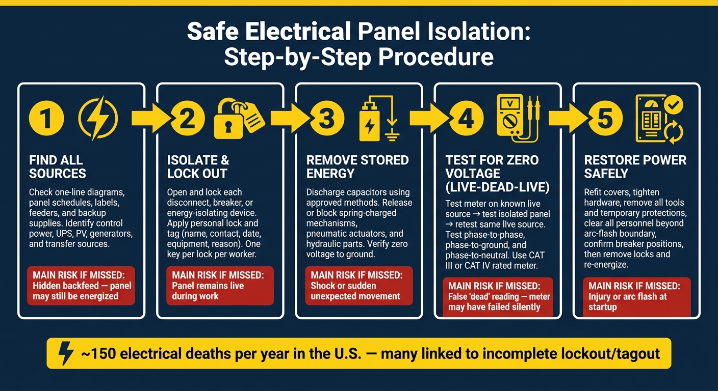
Electrical Panel Safe Isolation: Step-by-Step Lockout/Tagout Procedure
Electrical Isolation Procedure | Lock Out Tag Out | Electrical How To
sbb-itb-501186b
2. Identify the Correct Isolation Point and Hazards
Before you isolate anything, map every power source feeding the panel. Start with the latest one-line diagrams, panel schedules, and equipment nameplates. On the drawings, confirm the panel’s source equipment, feeder breaker number, voltage, and any listed alternate or emergency sources. Then check the field. Trace conduits and cables back to the source where you can, and make sure the panel identifier matches the drawings and the schedule.
Once you’ve mapped the sources, isolate each one.
2.1 Local disconnects, upstream feeders, and backfeed sources
The local disconnect is the first isolation point. It is not the only one.
It may shut off the feeder conductors to that panel, but upstream devices, control power circuits, or alternate sources may still be live. If the one-line shows the panel fed from a main switchboard, motor control center, or automatic transfer switch, check whether the bus can be energized by utility power, generator power, or both.
Backfeed sources are easy to miss, and that’s where people get burned. Include every possible path in the lockout/tagout plan, such as:
- Control power
- UPS units
- Battery systems
- PV sources
- Standby generators
- Transfer or tie sources
2.2 Check panel labeling against the field installation
Panel labels and circuit directories help you identify equipment, but they do not confirm de-energization.
A label may be wrong, old, or never revised after a change. Compare the panel nameplate to the one-line diagram, then physically trace conduits and cables from the panel back toward the source where possible. Check conductor size and conductor count against the drawings.
Pay attention to warning signs in the field: handwritten directories, scratched-out notes, “TBD” markings, or breakers marked as spare that are plainly in use. If the drawings and field conditions don’t match, treat that as unresolved until you trace and test it. If the records and the installation disagree, the isolation plan is not reliable yet.
2.3 Table: Common isolation points and residual risk
| Isolation Point | What It Controls | Residual Hazards |
|---|---|---|
| Local panel disconnect | Primary feeder conductors to that panel | Backfeed sources, control power, and adjacent live parts may remain energized |
| Upstream main disconnect (switchboard/MCC) | Multiple downstream feeders from that bus | Emergency, generator, or PV sources connected through transfer or tie devices may still be live |
| Feeder breaker (in switchgear lineup) | One feeder to a downstream panel or load | The line side of the breaker and the bus remain energized; nearby live sections can still present arc flash risk |
| Locked panel breakers (branch/load isolation) | Specific loads or branch circuits only | The panel bus remains energized; shared neutrals or control circuits may still carry voltage |
Each isolation point in this table covers a different part of the power path. In most commercial and industrial panel work, you’ll need more than one of these steps used together. With every source identified, isolate and lock out each one before opening the enclosure.
3. Isolate, Lock Out, and Control Stored Energy
Once you've mapped every power source, the next step is to physically isolate the panel by opening and locking each energy-isolating device. That starts with opening and locking the disconnect, not just flipping it off. The isolating device should be locked before any panel cover comes off.
3.1 Apply lockout/tagout to the disconnect
Apply lockout/tagout to every isolating device you identified in the field. When the disconnect is in the open position, place your lock and tag directly on the energy-isolating device and make sure the lock is secure. Under OSHA 29 CFR 1910.147, only authorized employees may install and remove lockout/tagout devices, and each worker must use a personal lock with one key per lock.
The tag should include:
- The worker's name
- Contact information
- Date and time
- Equipment
- Reason for lockout
If your site uses a permit-to-work system, the tag details should match that permit record.
Pushbuttons and selector switches are control devices, not isolation devices. They don't open the circuit. The disconnect, breaker, or switch that mechanically opens the circuit is the device that needs to be locked out.
Site procedures should spell out who can apply and remove locks, and who can approve re-energization.
3.2 Discharge and secure stored energy
A lock doesn't remove every hazard. After LOTO is in place, all stored energy has to be relieved before anyone accesses the panel.
Capacitors can stay charged even after power is removed. Discharge them with manufacturer-approved methods, such as built-in bleed resistors, grounding discharge circuits, or automatic discharge systems. Then verify that voltage between terminals and to ground reads zero before moving ahead.
Stored mechanical energy matters too. Spring-charged breaker mechanisms, pneumatic actuators, and hydraulic parts can move without warning if they aren't restrained or depressurized. Release or block them before any internal access. If stored energy can build up again during the job, keep checking isolation until the work is done.
Then turn your attention to nearby energized parts and any downstream exposure.
3.3 Guard against adjacent live parts and downstream exposure
Even when the target panel is fully isolated, the area around it may still be energized. Line-side conductors feeding the disconnect remain live. Downstream circuits may also backfeed the panel through other backfeed paths. Nearby live sections can still expose workers to shock or arc flash.
Use temporary barriers, insulating blankets, or blank covers over any live busbars or terminals within reach of the work area. Close and secure all unaffected cabinets. If the electrical room has multiple panels or mixed-voltage equipment, clearly mark the work-zone boundary and restrict access to anyone who isn't directly involved.
When other workers are nearby, say clearly which sections still have power. Don't assume they already know. A short verbal confirmation or a posted warning sign at the access point can stop a bad mistake in a busy electrical room. After isolation and discharge, verify zero voltage before opening the panel.
Next, test for zero voltage before opening the enclosure.
4. Verify the Panel Is De-Energized Before Opening
Once the locks are on and stored energy has been dealt with, the next step is simple but non-negotiable: verify absence of voltage at the point of work. The only way to confirm zero voltage is to test at the point where the work will happen with a properly rated meter. OSHA and NFPA 70E both treat this as a required step, not something you do only if you feel unsure.
4.1 Use the live-dead-live method
Use the live-dead-live method every time. You may also hear it called prove-test-prove. The idea is straightforward:
- Test the meter on a known live source
- Test the isolated panel
- Test the same live source again
That three-step check shows two things: the meter worked before the panel test, and it still works after it. Without that last check, you can't be sure the meter didn't fail during testing.
Use a known live source in the same voltage class as the circuit you're checking. Set the meter to the right voltage range, confirm the expected reading, and then move to the locked-out panel. After testing the panel, go back to the same live source and confirm the meter still reads as expected. If that last check fails, stop. Replace the meter or the leads before doing anything else.
Before testing, give the meter, leads, and probes a careful visual check. Look for damaged insulation, cracked housings, or other visible problems. For distribution panel work, use a meter rated CAT III or CAT IV, and make sure the leads have the same rating or a higher one. A cheap tester, or one with the wrong rating, doesn't cut it.
4.2 Test every relevant conductor combination
Test every relevant conductor, not just the obvious ones.
On a three-phase 480 V panel, test:
- Phase-to-phase
- Phase-to-ground
- Phase-to-neutral, if neutral is present
On a single-phase 120/240 V panel, check line-to-neutral, line-to-ground, and line-to-line across both hot conductors. Also verify neutral-to-ground where that applies.
And don't stop at the main breaker lugs. Test the incoming and outgoing conductors tied to the task, including bus bars, breaker load terminals, control power terminals, and feeder lugs. This is where people can get tripped up. A panel can look shut down, but a separate 120 V control transformer or a UPS-fed circuit may still be live even with the main disconnect open. That's why those circuits need testing too, along with their common and ground reference points.
4.3 What to do if readings do not match expectations
If you see voltage where zero should be, stop work immediately. Don't remove covers. Don't reach into the enclosure.
Unexpected voltage can come from residual charge, backfeed, mislabeling, or a shared neutral path. In other words, something in the isolation plan isn't lining up with what the meter is telling you.
To tell the difference between a hazardous source and induced voltage, use a low-impedance tester. Induced voltage from nearby parallel conductors will often drop away under a small load. A real backfeed source usually stays near system voltage. If the reading holds, treat the circuit as live.
At that point, go back to the one-line diagrams, retrace the source, and confirm each isolation point before any panel access continues. If the source can't be pinned down right away, notify your supervisor and bring in qualified personnel. Do not open the enclosure until the readings match the isolation plan.
5. Complete the Work and Restore Power Safely
Once the meter shows zero voltage and the work inside the panel is done, it’s time to put the system back in service. This part calls for the same care as shutoff. A rushed restart can undo all the good work that came before it.
5.1 Pre-energization checks before removing locks
After zero voltage is confirmed, start the re-energization checklist before removing any lock. The authorized employee should verify that the job is finished, all terminations are torqued to the manufacturer’s specs, and no more work is planned inside the panel. Then do a visual check. Make sure each conductor is landed where it belongs, insulation is in good shape, and there are no exposed live parts or loose components.
Next, remove temporary protections in the approved sequence. That includes temporary grounds, barriers, protective blankets, insulating shields, and jumpers. Each one should be accounted for and removed under the facility procedure. Reinstall the dead-fronts, side shields, and main panel cover, and tighten all hardware so the enclosure is fully secured.
When the panel is physically clear, confirm that all tools, test leads, parts, and debris are out of the area. Also make sure all personnel are outside the arc-flash boundary and know that power is about to be restored. In commercial and industrial settings with more than one crew, this means direct communication with each crew lead, not just a quick look around. Check that breakers, disconnects, and control switches are in the right position and that the equipment will not start on its own when power comes back.
Only then should the authorized employee remove the locks and tags and re-energize the upstream source, while standing to the side and wearing the right PPE. After that, notify affected employees and operators that servicing is complete and the panel is back in service. Finish with any required functional checks, including correct voltage, phase rotation, and protective-device operation.
5.2 Documentation and equipment readiness
Once the panel is back in service, document the job right away. Update the panel schedule to show any circuit changes, new loads, or replaced devices. NEC Article 408.4 says circuit directories must be accurate, legible, and durable. If you changed the panel, you need to update the directory too.
Any affected source markings, fault-current labels, and one-line diagrams should also be updated before the next crew relies on them. Old labels can cause the next person to walk into the wrong problem with the wrong plan.
Document what turned up during the job, such as mislabeled feeders, unexpected backfeed sources, or devices that failed testing. Record the lockout/tagout event, test results, and any corrective actions so the next team has a clear record to work from. If the job exposed damaged breakers, disconnects with interrupting ratings that are too low, obsolete equipment, or other non-compliant components, replace them before the panel is treated as ready for normal operation.
FAQs
What counts as a backfeed source?
A backfeed source is any outside power supply that can keep terminals or equipment energized even after the main disconnect is turned off.
Common examples include UPS systems, energized external circuits, and MCC panels. These can create serious shock hazards for technicians working upstream. That’s why every power source needs to be identified, isolated, and clearly labeled for possible residual voltage.
Why isn’t turning off the panel disconnect enough?
Turning off the main disconnect does not guarantee a zero-energy state.
A panel can still have other live sources, such as control circuits or external feeds. It can also hold stored energy, like capacitive charge.
Before work starts, identify every energy source, apply lockout/tagout, and verify absence of voltage at all points with a calibrated meter.
What should I do if my meter shows unexpected voltage?
If your meter shows voltage you didn’t expect, treat the equipment as energized and stop work right away. Don’t keep going until you’ve checked for absence of voltage again at all points with a tester rated for the system’s nominal voltage.
Use the Test-Check-Test method. First, verify your meter on a known live source. Then check the equipment. After that, verify the meter again on a known live source.
If voltage is still present, look into possible backfeed from UPS systems, multiple power inputs, or improper neutral-to-ground bonds.





