




How Flywheel Storage Supports Grid Stability
Flywheel storage helps keep the grid steady when power conditions change in a split second. I’d sum it up like this: flywheels store energy in a spinning rotor, send power back in under 1 second, support voltage through inverters, and bridge short outages for about 15 seconds to a few minutes.
Here’s the short version if you want the answer fast:
- Best use: frequency control, voltage support, power quality, and short backup
- Main strength: very fast response, often milliseconds to under 1 second
- Main limit: short discharge time, so it’s not for multi-hour storage
- Common U.S. interconnection points: 480 V, 600 V, 4.16 kV, 12.47 kV, 13.2 kV, and 34.5 kV
- Typical hardware: spinning rotor, bearings, vacuum enclosure, motor-generator, inverter, relays, and controls
- Good fit for: substations, solar-heavy feeders, EV charging sites, data centers, hospitals, and microgrids
I’d also keep three numbers in mind:
- U.S. grid inertia has fallen by about 6% in the Eastern Interconnection and 15% in the Western Interconnection
- Flywheels can move to full output in under 100 milliseconds in some systems
- Beacon Power’s Stephentown project is rated at 20 MW / 5 MWh, or about 15 minutes at full output
What this means for you is simple: flywheels are built for high power over short time windows. They don’t shift energy across the day like long-duration storage. Instead, they act more like grid shock absorbers, handling sudden dips, surges, voltage swings, and transfer gaps before slower assets step in.
If I were reducing the full article to one takeaway, it would be this: flywheels fit jobs where speed matters more than duration.
How Flywheel Systems Work and What They Connect To
Core Parts: Rotor, Bearings, Enclosure, Motor-Generator, and Controls
A flywheel system comes down to two big pieces: mechanical storage and electrical control. The mix of hardware on both sides shapes how fast the system reacts and how it ties into the grid.
The rotor is the center of the whole setup. High-strength steel or carbon-fiber rotors spin at 20,000–50,000 rpm and store energy as kinetic energy. Carbon-fiber designs can store more energy in less mass, and the rotor’s speed plus its strength-to-weight ratio set the storage limit while staying within safe stress ranges.
Bearings have a big effect on friction, wear, and upkeep. Rolling bearings are simpler and lower cost, but they wear out sooner. Active magnetic bearings (AMBs) reduce friction, support very high cycle life, and use catcher bearings for fail-safe spin-down. In plain terms, the bearing choice affects how well the system can handle nonstop fast cycling for regulation service.
The vacuum enclosure does two jobs at once: it reduces air drag losses and helps contain rotor failure.
On the electrical side, a permanent-magnet motor-generator manages both charging in motor mode and discharging in generator mode. It connects to the grid through a bidirectional IGBT inverter, which gives the system millisecond-scale response. DSP/FPGA, PLC, and SCADA controls manage rotor speed, vacuum conditions, and grid dispatch commands. Relays protect the system from vibration, high temperature, and overspeed.
Power, Energy, and Response Time in Practical Terms
It helps to separate power from energy right away. Power, measured in kW or MW, tells you the output rate. Energy, measured in kWh or MWh, tells you how long that output can last.
Flywheels are built for high power over short periods. Beacon Power's Stephentown plant combines 200 modules into a 20 MW/5 MWh system, which works out to about 15 minutes at full output.
For grid services, engineers usually size power first based on the job the system needs to do. After that, they pick energy capacity to cover the expected dispatch window. Frequency regulation and synthetic inertia need MW-scale power with seconds-to-minutes of energy. Short-duration backup needs enough power for the critical load, with energy sized for the handoff until a generator or battery system takes over - usually 15 seconds to a few minutes. That power-first approach is why flywheels fit regulation and ride-through so well, but not bulk energy shifting.
Where flywheels stand out most is response time. Advanced systems can move from idle to full output in under 100 milliseconds, with the main limit coming from the power electronics. Beacon Power's Stephentown data showed the plant delivering the full 20 MW up or down in under 4 seconds, which is comfortably inside NYISO's 6-second requirement. That kind of speed is why flywheels work so well for sub-second frequency regulation and synthetic inertia.
Interconnection Equipment for Medium-Voltage Distribution Systems
Once the machine size is set, the next step is figuring out how it connects to the feeder. Flywheel modules usually run at 480 V or 600 V and connect to distribution feeders through a step-up transformer, switchgear, relays, and metering. Protection coordination matters here because the power flow is fast and bidirectional.
About 80% of North American distribution operates in the "13 kV class" - meaning 12.47 kV, 13.2 kV, 13.8 kV, or 14.4 kV. Interconnection at 4.16 kV is common at industrial sites and in older urban systems. 34.5 kV is common at subtransmission interconnection points for larger installations.
The transformer has to handle both real and reactive power. Its impedance and tap settings also need to line up with protection coordination and voltage support needs. A delta-wye winding setup can help with ground fault exposure and harmonic issues from the inverter.
Medium-voltage switchgear - metal-clad or metal-enclosed lineups - contains the circuit breakers, contactors, and disconnects for the flywheel feeder. Protection relays cover over/under-voltage, over/under-frequency, reverse power, and anti-islanding, all aligned with IEEE 1547-2018 interconnection requirements. Revenue-grade metering tracks MW, MVAr, MWh, and power quality data for ISO/RTO participation and internal performance checks. Control and communication interfaces - usually DNP3 or IEC protocols - link the flywheel controller to plant SCADA or utility dispatch systems for real-time frequency and voltage support commands. That link is what allows flywheels to take part in feeder upgrades, substation work, and local voltage support.
These specs shape how flywheels provide fast frequency support, which comes next.
sbb-itb-501186b
How Flywheels Support Frequency Control and Synthetic Inertia
Fast Frequency Regulation in Seconds and Sub-Seconds
Once they're connected, flywheels can correct frequency swings almost at once. The U.S. grid runs at 60 Hz, so even small supply-demand mismatches can cause trouble. When generation and load slip out of balance, flywheels can send power into the grid when frequency drops or soak up power when frequency climbs. And they do this automatically, without delay. In grid operations, that role is called primary frequency response.
This is where flywheels shine. They match primary response and enhanced frequency response well, especially in cases where reaching full output within 1 to 10 seconds is what counts.
Synthetic Inertia and Rate-of-Change-of-Frequency Response
Flywheels do more than frequency regulation. They can also act like inertia during sudden grid events. As more non-synchronous renewables take the place of thermal plants, the grid loses part of the natural inertia that used to slow frequency changes after a disturbance. That means frequency can move faster - and that gives operators less time to react.
Flywheels help by providing synthetic inertia. In plain English, they can inject power when the frequency is changing at a high rate, or RoCoF. That support can help keep system frequency above under-frequency load-shedding thresholds.
There’s an important control detail here. Grid-forming inverters support frequency right away because they don’t depend on a phase-locked loop. Grid-following inverters respond only after a measurement delay, which makes them a better match for fast frequency response than for true synthetic inertia.
Where Frequency Support Fits Best
Flywheels work best in jobs where fast, repeatable cycling matters more than storing energy for hours. Put simply, they’re a strong match for short bursts of grid support, not long-duration energy shifting.
That makes them a good fit for:
- Microgrids, where they can steady the system during the switch between grid-connected and islanded operation
- Feeders with high solar penetration, where they can smooth weather-driven solar swings
| Feature | Conventional Rotating Inertia | Flywheel-Based Synthetic Inertia |
|---|---|---|
| Response Speed | Instantaneous (physical/natural) | Near-instantaneous (GFM) or <1 second (GFL) |
| Controllability | Fixed by machine physics | Fully programmable and optimizable |
| Siting Flexibility | Limited to large power plants | High; deployable at distribution or microgrid level |
That mix of speed and control makes flywheels a strong choice for distribution and microgrid projects that need rapid, short-duration support.
How 40-Ton Spinning Wheels Are Saving the Power Grid
How Flywheels Provide Voltage Support, Power Quality, and Short-Duration Backup
Beyond frequency response, flywheels also help steady feeder voltage and shield sensitive loads.
Voltage Regulation and Reactive Power Support
The same inverter used for frequency control can also provide local voltage support on distribution feeders. It can inject or absorb VARs without depending on rotor speed. That matters when motor starts or solar swings cause voltage sags. In those moments, the inverter can react in under 20 milliseconds.
This fast response also helps with flicker from industrial loads such as arc furnaces and welders. Instead of letting those swings ripple through the feeder, the flywheel can smooth them out with sub-second power injection or absorption.
Power Quality Support for Dynamic Loads
EV fast chargers and industrial drives can put real strain on local feeders. They pull power in sharp bursts, which can upset feeder voltage and add harmonics. A flywheel sits between those loads and the rest of the circuit, soaking up the spikes before they spread across the feeder.
Some converters can also filter harmonics from nonlinear loads and support IEEE 519 compliance. That makes flywheels a good fit for industrial plants and EV charging hubs where harmonic distortion is a concern.
Those same fast controls also make flywheels useful for bridging brief outages.
Short-Duration Backup and Ride-Through for Critical Operations
When utility power drops, there is usually a short gap before a standby generator starts and synchronizes. A flywheel can cover that gap with no interruption until the generator takes over. For sites that need zero-break power transitions, that pairing makes a lot of sense.
In practice, flywheels are best suited for sub-second frequency support, fast voltage correction, power-quality smoothing, and short ride-through, not long-duration backup.
Planning Flywheel Storage in Distribution Upgrades
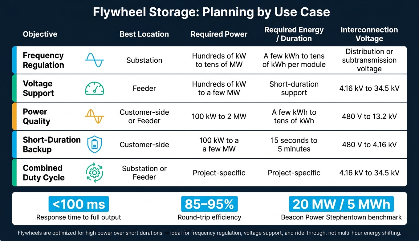
Flywheel Energy Storage: Use Cases, Specs & Grid Applications at a Glance
Once the service is defined, size the flywheel around the grid problem, not just the equipment list.
Define the Objective, Site, and Electrical Interface First
Start with the grid need. That sets the power, duration, site, and interconnection requirements.
A simple use-case matrix helps tie the need to clear targets. For frequency regulation, define the required MW capacity, response time under 1 second, and the ramp rate needed to follow automatic generation control (AGC) signals. For voltage support, set the reactive power target in MVAr and the allowed voltage band at the point of interconnection, often around ±5%. For short-duration backup, specify the real-power rating in kW or MW and the ride-through window, which is usually 15 seconds to 5 minutes for critical loads. If the system will handle more than one job, set service priorities, expected daily cycles, and dispatch rules so EMS, DMS, and SCADA commands don’t clash.
After that, pick the location based on what the system needs to do. Substation-level siting makes the most sense when the goal is broad frequency support, primary voltage control, and fault ride-through across several feeders. Feeder-level placement is better for voltage stability and power quality on circuits with heavy solar PV, big industrial loads, or frequent voltage flicker. Customer-side installation fits critical facilities like data centers, hospitals, semiconductor fabs, and microgrids that need sub-second ride-through and power quality conditioning.
The electrical interface comes next. In the U.S., common interconnection voltages include 4.16 kV, 12.47 kV, 13.2 kV, and 34.5 kV. Transformer and grounding design need to support bidirectional power flow and match the protection scheme. Protection coordination should cover overcurrent, differential, undervoltage, overvoltage, frequency deviation, and anti-islanding relays in line with IEEE 1547 and utility interconnection rules. Communications with EMS, DMS, or SCADA usually rely on DNP3, Modbus, IEC 61850, or TCP/IP. Typical data points include MW, MVAr, rotor speed, and alarms, along with latency targets under 200 milliseconds and cybersecurity controls tied to NERC CIP requirements.
Check Ratings, Environment, Standards, and Lifecycle Costs
System sizing should come from actual grid event data, not guesswork. That means using historical frequency deviation records, voltage sag logs, or outputs from power quality monitors.
The DOE/Beacon Power 20 MW flywheel frequency regulation plant cycles between 3,000 and 5,000 full depth-of-discharge cycles per year at 100% DoD and has operated at about 99% availability.
Site conditions matter more than many teams expect. Standard flywheel equipment usually operates between 32°F and 104°F. In hotter climates, sites may need air-conditioned or insulated enclosures. In colder areas, heating or insulation may be needed to limit condensation. Foundations should use reinforced concrete with vibration isolation, and noise levels should be checked against local rules. The Stephentown plant uses underground concrete housings for each unit to help contain noise and manage safety risk.
On the cost side, lifecycle analysis in USD should include capital expenditure, scheduled maintenance intervals, round-trip efficiency of 85% to 95%, and the expected lifetime cycling profile. That’s where flywheels can look strong in NPV and LCOS work, since high cycle life changes the math.
Conclusion: Where Flywheels Fit Best in Smart Grid Projects
Flywheels are best for fast-cycling, short-duration work, not multi-hour energy shifting. They fit frequency regulation, voltage support, power quality smoothing, and bridging the gap to a standby generator.
The table below sums up the main planning variables by use case.
| Objective | Location | Required Power | Required Energy | Interconnection Voltage |
|---|---|---|---|---|
| Frequency regulation | Substation | Hundreds of kW to tens of MW | A few kWh per module to tens of kWh | Distribution or subtransmission voltage, depending on the site |
| Voltage support | Feeder | Often hundreds of kW to a few MW | Short-duration support | 4.16 kV to 34.5 kV |
| Power quality | Customer-side or feeder | 100 kW to 2 MW | A few kWh to tens of kWh | 480 V to 13.2 kV |
| Short-duration backup / ride-through | Customer-side | Often 100 kW to a few MW | Short-duration support | 480 V to 4.16 kV |
| Combined duty cycle | Substation or feeder | Project-specific | Project-specific | 4.16 kV to 34.5 kV |
FAQs
Why are flywheels better for short bursts than long backup?
Flywheels are built for high power density and very fast response. So when the grid sees load swings or sudden power spikes, they react fast and handle those changes well.
That’s why flywheels work so well for frequency regulation and short-term grid stability.
The tradeoff is simple: they have lower energy density. In plain English, they can deliver a lot of power fast, but not for very long.
So they’re best for rapid power support, not long-duration backup.
How do flywheels stabilize solar-heavy feeders?
Flywheels help stabilize solar-heavy feeders by softening the swings in solar output that happen when clouds pass or weather shifts.
Because they have high power density and respond almost instantly, they can absorb or release kinetic energy in a flash. That helps keep supply and demand in balance, supports steady frequency and voltage, and eases stress on grid equipment.
What should I check before interconnecting a flywheel system?
Before interconnecting a flywheel energy storage system, start with grid feasibility. Check the available substation capacity and the megawatt headroom for both export and import. You also need to confirm who manages the connection point: a distribution operator or a transmission operator.
Then look at the electrical limits at the point of interconnection. Review busbar limits, fault current, protection settings, and relay coordination. Make sure the switchgear interrupting ratings are adequate, confirm compliance with IEEE 1547-2018 and NEC 705, 706, and 710, and verify that the existing transformers and switchgear match the system design.





