




Substation Site Preparation: 8 Planning Points
A substation site can fail before the first piece of equipment arrives. If I get the fence line, pad spacing, grounding, drainage, roads, lighting, staging, and permits lined up early, I cut down the odds of unsafe touch voltage, flooded equipment, blocked crane access, and field rework.
Here’s the short version:
- I start with site inputs: voltage class, equipment count, soil data, flood risk, delivery route, and future expansion
- I set the yard boundary around clearances, security, and access
- I size pads and spacing from actual equipment dimensions and weights
- I build the grounding grid and surface rock for safe step and touch voltage
- I grade the site for 1% to 2% drainage and check flood elevation targets
- I plan roads for the largest truck, trailer, and crane, not the average one
- I light the yard for both security and night work
- I keep laydown space and permit limits from boxing in future work
A few numbers stand out fast: fences for outdoor installations over 1,000 V are often 7 ft or more, yard rock is often 3 to 6 inches deep, access roads are often 20 to 24 ft wide, and many sites plan drainage around at least a 100-year storm.
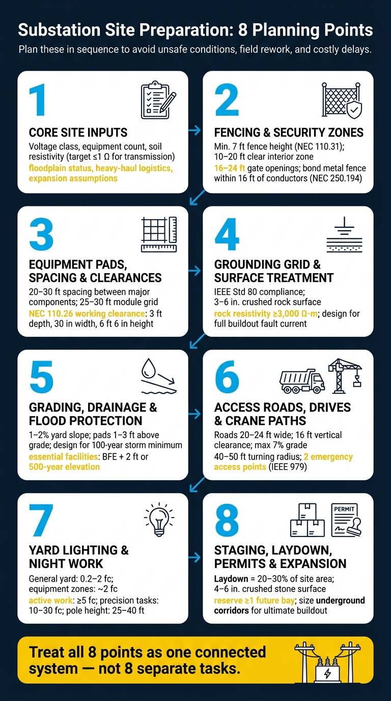
Substation Site Preparation: 8 Planning Points Checklist
Substation Layout
sbb-itb-501186b
Quick Comparison
| Planning point | What I check first | What can go wrong if I miss it |
|---|---|---|
| Fencing and security | Fence height, clearance, gate width, bonding | Access issues, clearance problems, touch voltage risk |
| Pads and spacing | Equipment size, weight, work clearances | Pads too small, blocked maintenance space |
| Grounding and surface | Soil resistivity, fault current, rock depth | Unsafe step/touch voltage |
| Grading and flood control | Slope, ponding, floodplain elevation | Water damage, erosion, muddy access |
| Roads and crane paths | Turning radius, load limits, vertical clearance | Delivery delays, crane setup problems |
| Lighting | Foot-candle targets, pole placement | Poor night visibility, glare, dark work zones |
| Staging and laydown | Space, surface prep, storage order | Congestion, damaged materials, blocked routes |
| Permits and future growth | Setbacks, approved limits, spare space | Redesign, permit delay, no room to expand |
If I treat site prep like one connected plan instead of eight separate tasks, the yard is much easier to build, use, and expand later.
Before the Layout Starts: Core Site Inputs
Before you start laying out anything, get the core site inputs in place. They shape almost every choice that comes next: the fence line, equipment pads, grounding, drainage, access roads, lighting, staging space, and room for future work. If you skip this step or guess too early, the whole site plan can drift off course.
Voltage class and equipment count set the basic size of the yard and the spacing between bays. Higher voltages need more clearance and more distance between structures. Then equipment count starts to snowball that footprint. More transformers, breakers, and line terminals mean more bays, more spacing, and more land. Even a rough count early on gives you a much better read on how big the site needs to be.
Soil bearing capacity and resistivity should be gathered at the same time because they affect two different design paths. Bearing capacity, measured in lb/ft², tells you whether spread footings are enough or whether heavy gear will need piles. Soil resistivity affects the grounding grid. High-resistivity soils, like dry sand or fractured rock, usually need denser copper grids and more ground rods to keep touch and step voltages within safe limits. Transmission substations often target a ground resistance of 1 ohm or less, while smaller distribution substations may land in the 1 to 5 ohm range based on site conditions and utility rules. Soil borings and resistivity testing done together, with the Wenner four-point method under IEEE 81, give the grounding designer actual numbers to work from.
Floodplain status and stormwater rules can change the yard elevation and drainage plan fast. If the site is in a FEMA-designated floodplain, the finished yard may need to sit above the base flood elevation with engineered fill. Substation drainage systems are often designed for 100-year storm conditions at minimum.
Heavy-haul delivery logistics are easy to underestimate and expensive to fix later. You need the largest transformer’s shipping weight, trailer dimensions, route limits, and crane pad needs before gates or internal drives are locked in. A gate that looks fine on paper can become a problem the minute a heavy-haul trailer tries to turn through it.
Expansion assumptions should be part of the input matrix from the start, not an afterthought. Some utility standards call for land to be held for at least three bays or one additional bay beyond immediate need, whichever is greater. That means setting aside room for future bays, line terminations, and voltage upgrades. It also means sizing the grounding grid and drainage system for the ultimate buildout, not just phase one. Otherwise, you end up tearing into a finished yard later just to extend systems that should have been sized once.
| Core Input | What to Collect | Why It Matters |
|---|---|---|
| Voltage class & configuration | kV level, bus scheme, bay count | Sets clearances, bay widths, and total footprint |
| Equipment count & ratings | MVA, transformer/breaker dimensions and weights in lb | Sizes pads, crane access, and staging areas |
| Utility/owner standards | Standard bay modules in ft, fencing specs, grounding criteria | Locks in spacing, security zones, and conductor arrangements |
| Soil bearing capacity | lb/ft², settlement risk, groundwater depth | Determines foundation type and crane pad requirements |
| Soil resistivity | Ohm-meters, test method (IEEE 81) | Drives grounding grid density and copper quantity |
| Floodplain & stormwater | FEMA flood zone, 100-year elevation, discharge limits | Sets finished yard elevation and drainage design |
| Heavy-haul logistics | Trailer weight/dimensions in lb and ft, turning radii, crane footprint | Aligns gate placement, internal drives, and staging areas |
| Expansion assumptions | Future bay count, replacement unit sizes, planning horizon | Reserves land and sizes infrastructure for ultimate build |
With those inputs nailed down, the first layout move is the fence line and the security buffer.
1. Fencing and Security Zones
The fence line is the first fixed boundary in the layout. It sets the rules for clearances, grounding, access routes, and the reserve space needed for everything inside the yard.
NEC Article 110.31 says outdoor installations over 1,000 V need a perimeter fence that is at least 7 ft high, or 6 ft high with a 1-ft extension made of three or more strands of barbed wire. In practice, many utilities go beyond that. Some standards call for 8 ft total height and line posts spaced no more than 10 ft apart, which is common on tight sites.
NEC 110.31 also sets horizontal clearances of about 10 ft for equipment up to 13.8 kV, 15 ft for 13.8 kV to 230 kV, and 18 ft above 230 kV. Most designers add 1–2 ft of extra room so they don’t end up right on the limit. That small buffer can save a lot of trouble later.
The fence also has to tie into the grounding plan. NEC 250.194 requires metal fences within 16 ft of exposed conductors to be bonded to the grounding electrode system. OSHA adds another layer: conductive fences must be grounded and isolated, grounded, or bonded when sections are removed or extended during construction. Inspection guidance usually places the metal fence at least 1.0 m - about 3.3 ft - inside the station ground grid boundary, including gate swing, to help control touch and step potential.
Security works best in layers, not with the fence alone. A common setup includes:
- A perimeter fence with a 10–20 ft clear zone inside it, kept free of storage, vegetation, and nonessential structures
- 16–24 ft clear gate openings so maintenance trucks and crane equipment can get through without a headache
- Fence placement on the ultimate build-out line, so the perimeter does not need to move when new bays are added
With the boundary in place, the next layout focus is equipment pads, spacing, and clearances.
2. Equipment Pads, Spacing, and Clearances
After the fence line is set, pad locations start to define the yard grid. These foundations carry the main yard equipment, so where they go tends to shape the spacing pattern across the whole site. Pads are reinforced concrete foundations built to ACI 318, with compacted subgrade, a granular base, and a finished surface set slightly above grade so water drains off the pad. Pad design needs to match vendor dimensions, equipment loads, and drainage needs.
Once pad locations are locked in, the next job is making sure there is safe working room between pieces of equipment. Spacing between major components is typically 20–30 ft or more. That distance is driven by fire separation guidance, maintenance access, and voltage-clearance rules under the NESC and IEEE design guides. Most yards use a 25 ft or 30 ft module so equipment rows and access aisles line up cleanly and stay open.
For equipment that may be worked on while energized, NEC 110.26 sets the minimum working clearances in front of the equipment. That includes:
- 3 ft minimum clear working depth
- At least 30 in of width, or the equipment width if it is greater
- A clear height of 6 ft 6 in
That area needs to stay completely open. No storage. No stacked material. No temporary laydown. If a crew can't step in and work without weaving around obstacles, the layout is doing its job poorly.
Pad layout should also make later equipment changes less painful. Standard pad sizes and bolt patterns can make future additions much easier and help avoid cutting out and replacing concrete later. That kind of foresight matters, especially when a yard grows in phases or when equipment gets swapped years down the line. Those clearances and pad locations also depend on a yard surface that can deal with faults and touch potential.
3. Grounding Grid and Surface Treatment
Once pad layout and clearances are locked in, grounding and surface treatment become the layer that helps make the yard safe. The grounding grid is a buried network of copper conductors and ground rods. Its job is to give fault current a low-impedance path and help keep touch and step voltages within the tolerable limits set by IEEE Std 80, the main U.S. guide for AC substation grounding.
Grid depth, conductor spacing, and rod locations should come from the fault current, clearing time, and soil resistivity data. In practice, spacing is usually tighter around major equipment and control buildings, where risk is higher. In lower-risk parts of the yard, spacing can open up, as long as the calculated voltages still pass. Ground rods are often placed at grid intersections, with extra attention around the perimeter, to help lower grid resistance and reduce ground potential rise (GPR).
The surface rock layer matters too. It works with the grid to cut touch and step risk by increasing the resistance between a person’s feet and the ground below. Substation yards often use 3 to 6 inches of crushed rock for this reason. Crushed rock usually has a resistivity of about 1,000 to 3,000 Ω·m when wet and 2,000 to 5,000 Ω·m when dry. Many utility specs call for yard finish rock with at least 3,000 Ω·m resistivity.
| Surface Condition | Typical Resistivity | Design Role |
|---|---|---|
| Bare soil | ~100 Ω·m | Reference condition in design examples |
| Crushed rock, wet | 1,000–3,000 Ω·m | Raises allowable touch and step limits |
| Crushed rock, dry | 2,000–5,000 Ω·m | Provides the highest surface resistance |
Some utility standards say the rock must be installed before the yard is energized. If that can’t happen and early energization is still needed, any uncovered area should be barricaded and marked clearly.
One point trips people up: compliance is not based on hitting one magic resistance value. What matters is whether the actual mesh and step voltages stay below the tolerable limits for the selected body weight, fault duration, and surface condition.
It also pays to think past phase one. Design the grounding grid for the full yard buildout, not just the first stage. If future bays are planned, extend the grid now. Then retest whenever the yard footprint changes or fault current levels shift.
Keep a full record of the inputs, calculations, drawings, and final mesh, step, and GPR results. That paper trail shows owners, regulators, and insurers exactly how compliance was established.
4. Grading, Drainage, and Flood Protection
Once the grounding grid is in place, the next job is water control. If drainage is poor, water can wear down foundations, speed up corrosion in wet zones, and create slick, unsafe areas for people and vehicles.
Grade the yard for positive drainage with a gentle 1–2% slope toward perimeter swales, ditches, or basins. Finished grades should push water away from pads and equipment. Equipment pads should sit several inches above the nearby yard grade, and the full substation pad is often built 1–3 ft above the surrounding ground, based on flood risk. A common design goal is simple: clear ponding within a few hours after heavy rain.
Open ditches and swales are often easier to inspect and maintain than buried pipe systems. They also tend to cost less and are less likely to clog. This work needs to be lined up early with grids, trenches, foundations, and roads. If not, the site can end up with low spots that hold water. Dry, firm ground also helps protect access roads and crane paths built later.
Flood protection often sets the finished site elevation. Use flood elevation targets to choose finished grade and protection levels:
| Protection Target | Typical Criteria |
|---|---|
| Essential facilities | Base Flood Elevation + 2 ft or the 500-year flood elevation, whichever is higher |
| Emergency power systems | Base Flood Elevation + 3 ft or higher per local design flood criteria |
| Critical federal actions | 0.2% annual-chance flood elevation or Base Flood Elevation + 3 ft, whichever is higher |
NERC has also warned that stations not previously susceptible to flooding may now be at risk, so legacy sites should be checked again from time to time. Common resilience measures include sealing cable trench penetrations, tying float switches into SCADA for remote water-level monitoring, and strengthening or sealing control buildings, including walls and roofs.
5. Access Roads, Internal Drives, and Crane Paths
Once grades and drainage are set, the yard still doesn't work if heavy equipment can't get in and move around. That's why access roads and internal drives in a substation are engineered for the largest and heaviest vehicle that may ever enter the site, whether that's a transformer transporter, mobile crane, or fire truck.
For layout and clearance, the usual targets are pretty clear:
- Primary access roads should be 20 to 24 ft wide
- Keep 20 ft of clear space around key equipment
- Limit grades to 7%, with short stretches of 8% to 10% only
- Use turning radii of 40 to 50 ft
- Maintain 16 ft of vertical clearance
Crane aprons and bay approaches need to be sized for outrigger loads, not day-to-day traffic. In the field, that often means locally thickened gravel or concrete pads at crane hardstand areas, sized for outrigger pressure and repeated lifts over time. For the rest of the road system, compacted aggregate base or another all-weather surface is common. Paving is usually kept for steep grades that tend to erode or where local rules call for it.
Fire access brings its own set of rules. IEEE 979 guidance calls for at least two emergency access points to the switchyard, spaced about half the yard's diagonal apart, so one blocked entrance doesn't shut out emergency crews. Gates and access points also should not be placed directly under overhead lines or next to large oil-filled transformers.
Heavy-haul replacement routes should be planned before the road alignment is finalized. That route study lays out crane positions and turning corridors. Just as important, those corridors need to stay clear of permanent ductbanks, cable trenches, and structures.
Once vehicles can get in and move through the yard, the next step is making sure crews can see what they're doing during night work.
6. Yard Lighting and Night Work Conditions
Once equipment can move through the yard, crews still need safe visibility after dark. In a substation, lighting usually does two jobs: security and task work. Security lighting stays on at lower levels. Task lighting is a separate, higher-output mode used for night work.
Set lighting by use, not just by a target number. General yard areas usually need 0.2 to 2 foot-candles. Equipment zones are often set at about 2 foot-candles. Active work areas need at least 5 foot-candles, and precision tasks often call for 10 to 30 foot-candles. Those numbers should match what people are doing in the space - routine patrols, maintenance, and night lifts - not just a light meter reading. Perimeter fence lines are commonly held to about 0.5 foot-candles.
A simple setup works best:
- Low-output security lighting for routine conditions
- Portable task lighting for night work
Pole placement matters more than it may seem. Keep poles from becoming climb points near the fence. Stay clear of overhead conflicts, and don’t place them where they interfere with crane routes. Run wiring in conduit or concealed raceways. Use weather-rated, sealed LED fixtures to cut glare and lower maintenance costs. Mounting heights of 25 to 40 ft can work, but only where clearances and crane paths allow.
It also pays to think ahead. Stub out spare conduits, panel capacity, and future pole bases from the start, so a new transformer bay or a longer fence line doesn’t force a lighting redesign later. Lighting should also reach laydown and crane zones without throwing glare back at operators.
7. Material Staging and Laydown Areas
With access routes and lighting set, the last layout task is staging. This part is less about raw square footage and more about where things sit and how they move. Put a laydown area in the wrong spot, and you add crane travel, traffic jams, and lost time.
On medium projects, set aside about 20–30% of the site outside the fenced yard for laydown. Larger transmission jobs may need 3–20 acres, and major assembly areas can run about 200 ft × 200 ft.
Place laydown zones next to the site and line them up with the heavy-haul route. Keep staging on ground that sits above flood-prone areas, especially if you're storing transformer oil drums or materials that don't handle moisture well. Long-term or nonessential storage should sit in a separate fenced area, not inside the active electrical yard.
After you pick the location, prep the surface. Grade the laydown area so it's flat or gently sloped. Then add 4–6 in. of crushed stone so forklifts, cranes, and heavy haul trucks can move without rutting the ground. Use open swales or ditches for drainage to keep water from pooling. And skip round river rock.
It also helps to divide the laydown area by material type and install sequence. Think of it like setting up a workshop: the items you need first and most often should be easiest to reach.
- Sensitive equipment such as relays, control cabinets, and bushings should go in weatherproof enclosures near the control building.
- Bulk materials like cable reels, conduit, and structural steel can be stored in clearly marked open rows with forklift aisles.
- OSHA 29 CFR 1926 Subpart H requires materials to be stacked, blocked, or interlocked to prevent collapse, and incompatible materials must be kept apart.
Reserve the delivery path and crane corridor at this stage too. If you don't, later transformer replacements or expansion equipment can end up blocked by permanent installations.
Next, lock in permitting and expansion room before the layout is finalized.
8. Permitting, Environmental Review, and Expansion Planning
Permitting sets the site envelope, so map approvals before civil design starts. Those approvals decide what can be built, where it can go, and how much space is left for later work. Most projects need zoning or land-use approval, grading, stormwater, building, driveway, and utility connection approvals. Large transmission projects can also trigger federal or state environmental review. If you wait too long, agency comments can force grading changes, fence moves, or drainage redesign.
For substation sites, environmental review often centers on stormwater runoff, erosion and sediment control, wetlands, endangered species, noise, and spill prevention. The job here is simple in concept, even if the paperwork isn't: turn those rules into fixed layout limits. Stay outside regulated buffers. Keep required setbacks from property lines and public roads. Hold construction disturbance inside approved limits. Put those limits directly on the civil drawings and the construction plan set so crews can see them clearly in the field.
After those approval limits are locked in, use them to protect future yard space. This is where teams often give away the cheapest path to expansion. Reserve contiguous land for at least one future bay or a second transformer position, and keep that space clear of permanent obstructions like stormwater basins, buried utilities, or fixed lighting poles.
Also check that underground corridors, duct banks, and DC systems are sized for ultimate buildout and future cable volumes. Spare conduit stub-ups and open corridor space for future breakers or control house additions are usually much easier to install during the first build than during a later expansion. Anyone who's had to reopen a finished yard knows how fast that gets painful.
The amount of permitting and environmental review depends on the project type:
| Project Type | Permitting Scope | Environmental Review Focus |
|---|---|---|
| Upgrade within existing fence | Typically limited; may use existing approvals with minor modifications | Construction impacts and any incremental noise/EMF |
| Footprint expansion | New or amended site plan, zoning checks, and updated environmental review | Land use conversion, visual and community impacts, setback rules |
| New substation | Full permitting package, zoning determination, and full NEPA/state review if applicable | Comprehensive analysis including alternatives, socioeconomic effects, and community opposition risk |
Show future bays, transformers, and cable routes on site plans so later additions stay inside the approved envelope.
Comparison Tables for the 8 Planning Points
Use the tables below for a fast side-by-side look at the main layout tradeoffs. Each one turns a planning point into quick decision checks.
Fencing and Security Zones
Start with the fence line. Then use this table to compare the main security choices.
| Fence Type | Typical Height / Profile | Security Level | Bond to Ground Grid | Cost | Best Fit |
|---|---|---|---|---|---|
| Galvanized chain-link, no top treatment | 6–8 ft | Minimal | Required | Low | Low-risk distribution yards |
| Chain-link with 3-strand barbed wire | 6–8 ft base + top treatment | Moderate | Required | Low–Medium | Standard utility substations |
| Chain-link with razor wire top | 6–8 ft base + top treatment | High | Required | Medium–High | Critical infrastructure, higher-security sites |
| Welded mesh / anti-climb | Site-specific | High | Required | High | Urban sites, public-facing locations |
| Anti-ram perimeter fencing or bollards | Site-specific | Very high | Fence bonded; barriers coordinated with site grounding | Very high | Critical transmission substations |
| Decorative / privacy fence | Site-specific | Low | Required if metallic | Medium–High | Community-sensitive urban sites |
Equipment Pads, Spacing, and Clearances
This table compares layout types by site limits and how easy they are to maintain over time.
| Layout Type | Voltage Class | Typical Pad Size / Footprint | Crane/Truck Access Envelope | Construction Complexity | Long-Term O&M Ease |
|---|---|---|---|---|---|
| Standard outdoor AIS | 15–69 kV | Moderate | Full access envelope | Low–Moderate | High |
| Standard outdoor AIS | 115–230 kV | Large | Large crane pads and generous turnaround space | Moderate | High |
| Compact AIS (tight site) | 15–115 kV | Reduced | Restricted; deliveries and staging require more coordination | High | Moderate |
| GIS / metal-clad indoor | 15–230 kV | Small building footprint | No outdoor crane swing needed | High | Moderate–High |
| Pad-mounted / skid-mounted | 15–35 kV | Minimal | Standard utility truck access | Low | High |
Grounding Grid and Surface Treatment
Use this table to compare common yard surface choices.
| Surface Option | Grounding Benefit | Touch/Step Voltage Performance | Maintenance Burden | Best Fit |
|---|---|---|---|---|
| Crushed rock (3–6 in. depth) over copper grid | High-resistivity layer reduces surface current | Strong; standard for utility yards | Low (periodic re-rocking) | Most U.S. outdoor substations |
| Concrete walkways over grid | Grid must still be designed independently | Good where concrete covers high-traffic zones | Low | ADA access paths, heavy-traffic work areas |
| Concrete slab or paved yard area | Grid beneath slab; bonding still required | Good if the grid is properly designed | Very low | Indoor or covered GIS stations, hardened work zones |
| Bare soil | None | Poor; seasonal moisture changes resistivity significantly | High | Temporary construction areas only |
Grading, Drainage, and Flood Protection
Drainage plans depend on flood risk, runoff, and oil-containment needs.
| Strategy | Best Climate/Region | Oil Containment Compatible | Permitting Complexity | Cost |
|---|---|---|---|---|
| Surface grading + swales | Most U.S. regions; well-suited for rural sites | Partial | Low | Low |
| Underground storm drain piping | Urban sites; high-rain regions | Yes, with proper inlets and separators | Moderate | Medium |
| Detention/retention basin | High-runoff sites; often used where local stormwater rules require it | No (separate containment needed for oil) | Moderate–High | Medium–High |
| Elevated equipment pads | Coastal, floodplain, and hurricane-risk areas | Yes | High | High |
Access Roads, Internal Drives, and Crane Paths
Keep light-duty access separate from heavy-haul routes. That one call early on can save a lot of headaches later.
| Road Type | Design Vehicle | Typical Surface | Typical Width | Overhead Clearance | Freeze-Thaw Performance | Cost |
|---|---|---|---|---|---|---|
| Light-duty gravel | Pickup or SUV | Compacted gravel | Narrow | Standard | Moderate | Low |
| Improved gravel / stabilized aggregate | Utility bucket truck, digger derrick | Crushed aggregate + geotextile | Moderate | Standard | Good | Low–Medium |
| Asphalt drive | Heavy utility vehicles | Asphalt over compacted base | Wide | 20 ft or more | Good with proper base | Medium |
| Reinforced concrete / transformer route | Crane, lowboy, heavy-haul trailer | Concrete over engineered subgrade | Very wide | 20 ft or more | Excellent | High |
Heavy-vehicle routes are often designed for 20 ft or more of overhead clearance, and utility criteria may require 20 ft or NESC Section 124, whichever is greater.
Yard Lighting and Night Work Conditions
This table compares lighting systems by power use, maintenance load, and spill-light risk.
| Lighting Approach | Energy Use | Maintenance Burden | Light Pollution Risk | Best Application |
|---|---|---|---|---|
| High-mast pole-mounted LED floodlights | Low | Low | Moderate–High | Large transmission yards |
| Lower pole-mounted LED fixtures along drives | Low | Low | Low–Moderate | Distribution substations, urban sites |
| Building-mounted wall packs (LED) | Very low | Low | Low | Control house entries, small yards |
| Legacy HID (metal halide / sodium) | High | High | Moderate | Older sites not yet upgraded |
| Motion-activated fixtures | Very low | Low | Very low | Low-traffic perimeter areas |
Material Staging and Laydown Areas
Use this table to compare staging areas by load capacity and how permanent they are.
| Staging Type | Load Capacity | Stormwater Risk | Transition to Long-Term Use | Best Application |
|---|---|---|---|---|
| Temporary gravel laydown | Moderate; suitable for forklifts and telehandlers | Low if graded properly | Easy to repurpose | Construction staging and short-term material storage |
| Permanent gravel or crushed rock storage area | Moderate to high | Low–Moderate | Good | O&M storage, cable reels, steel, and pallet staging |
| Concrete laydown pad | High; suits pallets, skids, and small transformers | Low when drained properly | Very good | Frequent deliveries, clean storage, assembly areas |
| Segregated hazardous materials / oil-filled equipment zone | High with containment | Managed through containment and drainage controls | Limited; dedicated use | Oil-filled equipment, hazardous materials, and spill-sensitive storage |
Permitting, Environmental Review, and Expansion Planning
Use this table to match the project type with permit burden and room for future growth.
| Scenario | Permitting Complexity | Typical Review Burden | Public Outreach / Hearings | Future Expansion Considerations | Best Fit |
|---|---|---|---|---|---|
| Standard new distribution substation in a typical municipality | Low–Moderate | Local planning, zoning, building, and stormwater review | Limited | Reserve room for additional equipment if possible | Greenfield distribution sites |
| New transmission substation or expansion in a sensitive or coastal area | High | Local, state, and environmental review; wetlands, endangered species, floodplain, noise, and visual impacts | Often required | Early space reservation for future bays and lines is especially important | Coastal or environmentally sensitive sites |
| Brownfield upgrade or expansion of an existing yard | Moderate–High | Existing site constraints, environmental review, and utility coordination | Sometimes required | Expansion depends on how much open yard space was reserved earlier | Retrofit and expansion projects |
Conclusion
Substation site prep works as one connected system. When you look at all eight planning points together, they help keep the yard buildable, safe, and set up for future growth.
The best layouts leave room for future bays and access routes before construction begins. That’s why expansion space needs to be set aside before the first concrete pour. If the site plan is weak, the result is often costly field rework. A strong plan helps cut delays, rework, and safety risk.
For equipment sourcing alongside site planning, Electrical Trader can support transformer, breaker, and distribution component procurement. When site prep and procurement move in step, commissioning stays on schedule.
A well-prepared substation site is one where every major decision supports safety, reliability, constructability, and long-term growth. It’s the base the whole build stands on.
FAQs
What site data should I collect first?
Start with a geotechnical assessment to confirm soil bearing capacity, groundwater depth, and compressibility. At the same time, check local zoning rules and utility easements early so you don’t run into headaches later.
Next, look at site access. That includes bridge load ratings, overhead clearances, and road width of at least 15 ft for heavy equipment. Then document elevation and drainage potential, and clear vegetation, debris, and other obstructions.
How do I plan for future expansion early?
Size for current and expected power demand, not just today’s load, and leave room and clearances for added equipment.
Plan for about 20% spare ducts in cable trenches. Extend the concrete pad beyond the transformer footprint. Design grounding from soil resistivity testing before construction. And keep maintenance and access space open so later additions stay serviceable.
What mistakes cause the most site rework?
The most common causes come down to grounding mistakes and the inspection problems that go with them. That includes multiple neutral-to-ground bonds, missing or misplaced bonding jumpers, incomplete grounding electrode systems, and grounding conductors that are wrong, loose, or undersized.
Another common trigger is poor high-voltage cable installation. In plain terms, that can mean bad trench or drainage setup, too much pulling or bends that are too tight, damaged joints or terminations, and weak commissioning or testing.





