
Steam Turbine Control Diagnostics
Steam turbine control systems are critical for power generation, managing turbine speed, load, and synchronization with the electrical grid. Modern systems combine digital controllers, actuators, and valves for precise steam regulation, ensuring stable operation at a consistent frequency (e.g., 60 Hz in the U.S.). Diagnostics play a key role in maintaining reliability, detecting issues like mechanical slack, valve hysteresis, or actuator faults before they cause failures.
Here’s what you need to know:
- How They Work: Control systems regulate steam flow via governor valves, load control, and exhaust pressure mechanisms, safeguarding turbines during emergencies like load rejections.
- Why Diagnostics Matter: Early fault detection prevents failures, extends equipment lifespan, and reduces unnecessary maintenance costs.
-
Recent Advances:
- AI systems like IPSO-LSTM improve fault prediction.
- Optoelectronic monitoring enables blade inspections without disassembly.
- CFD models enhance axial thrust predictions, reducing wear.
- Maintenance Benefits: Diagnostics shift from fixed schedules to condition-based maintenance, saving up to $200,000 per inspection cycle while doubling overhaul intervals to 100,000 operating hours.
Diagnostics are transforming turbine maintenance, making operations safer, more efficient, and cost-effective.
How the Steam Turbine Control valve and Stop Valve system works |Steam Turbine | Vojtech kucirek
sbb-itb-501186b
Recent Studies on Instrumentation and Control
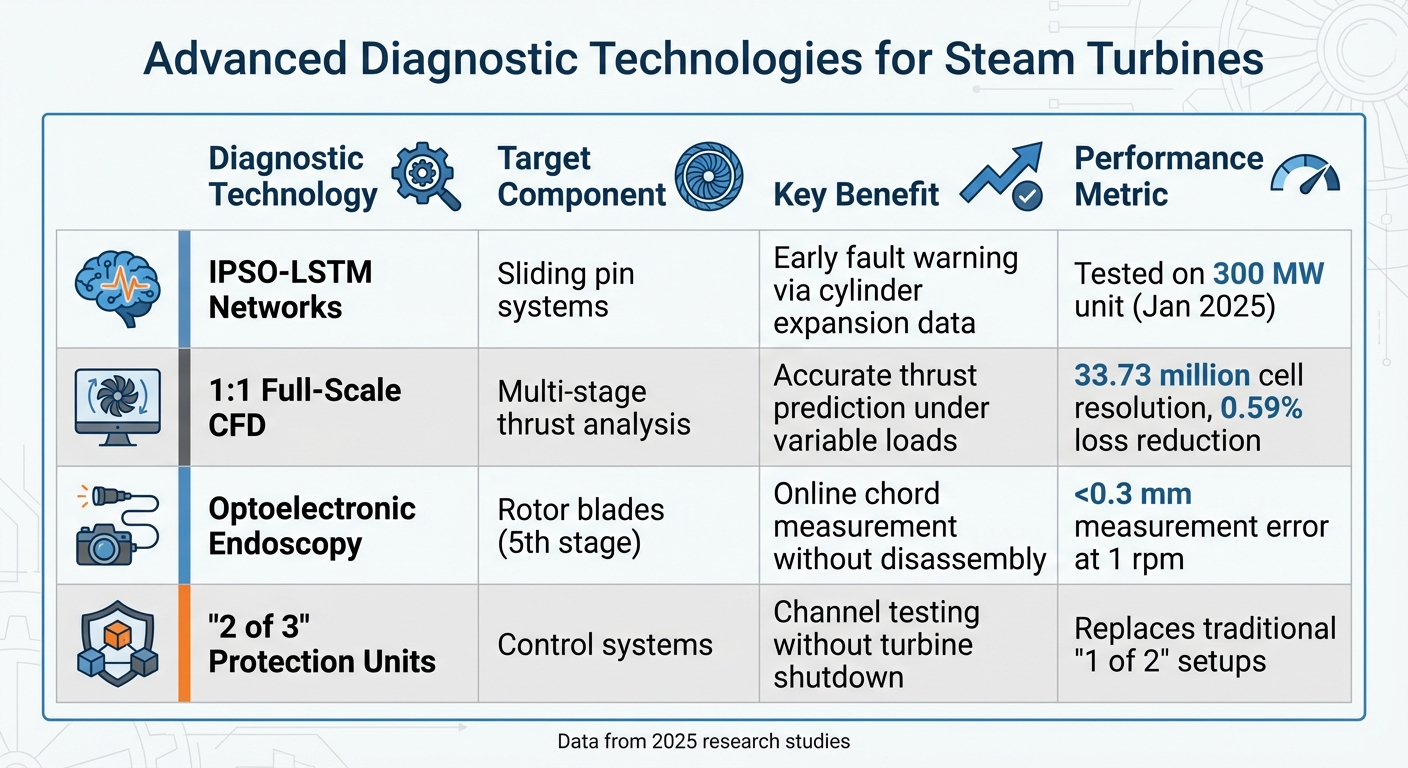
Steam Turbine Diagnostic Technologies Comparison Chart
Key Findings from Recent Research
Recent studies have zeroed in on improving the reliability and monitoring of steam turbine control systems. A major area of progress lies in protection system architectures. Traditional "1 of 2" setups in modern electrohydraulic control systems (EhACS) are being phased out in favor of "2 of 3" or "n-1 of n" protection schemes. These updated configurations allow individual channel testing without requiring a turbine shutdown. For instance, the Ural Turbo Engine Plant revamped its protection system by modifying the automatic lock of the stop valve, reducing the number of valves while maintaining safety standards.
Another significant advancement is the use of artificial intelligence for fault prediction. A system combining Improved Particle Swarm Optimization (IPSO) with Long Short-Term Memory (LSTM) networks has been developed to monitor sliding pin systems. In January 2025, this method was tested on a 300 MW unit, using cylinder expansion measurements to predict potential failures. By analyzing time-series data, the system identifies anomalies early, addressing the limited sensor coverage of conventional control systems.
Control valve performance has also been a focus, particularly regarding flow-induced vibrations. Research at Technische Universität Dresden revealed that spherical valve designs can cause unstable flow patterns during part-load operations, leading to vibrations and dynamic loads. Engineers have found that adding separation edges, such as Backstep or Cutoff geometries, helps stabilize the flow. Christian Windemuth, from the Chair of Turbomachinery and Flight Propulsion, highlighted:
the magnitude of vibrations is linked to the stability of the flow field, which in return is dependent of the geometric design and the operating point.
These design modifications have been shown to increase subsonic flow rates by 20–30% at specific valve opening ratios.
These advancements are paving the way for more sophisticated diagnostic tools that can further improve turbine maintenance.
New Developments in Diagnostic Technologies
High-fidelity computational modeling has become an essential diagnostic tool. Researchers at the State Key Laboratory of Clean and Efficient Turbomachinery Power Equipment have developed full-scale CFD models with grid resolutions up to 33.73 million cells. These models provide highly accurate predictions of axial thrust, a key factor in preventing bearing wear and rotor displacement. Fangfang Song explained:
the blade root hub is the primary source of the total axial thrust, exhibiting a near-linear relationship with mass flow rate under partial loads - a crucial insight for precise thrust forecasting.
This research also optimized mixing chamber geometries, reducing regulating stage losses by 0.59% under Valve Wide Open conditions.
Another breakthrough is in optoelectronic monitoring systems, which now enable blade inspections without disassembly. In February 2025, researchers validated a method for monitoring fifth-stage blade wear using video endoscopy. This approach measures rotor blade chord lengths during shaft rotation, with pixel-by-pixel software processing achieving measurement errors below 0.3 mm. These systems meet industry standards for repair decisions and can operate at rotor speeds up to 1 rpm, using differential illumination to counteract reflection variations caused by erosion and corrosion.
| Diagnostic Technology | Target Component | Key Benefit |
|---|---|---|
| IPSO-LSTM Networks | Sliding pin systems | Early fault warning via cylinder expansion data |
| 1:1 Full-Scale CFD | Multi-stage thrust analysis | Accurate thrust prediction under variable loads |
| Optoelectronic Endoscopy | Rotor blades | Online chord measurement with <0.3 mm error |
| "2 of 3" Protection Units | Control systems | Channel testing without turbine shutdown |
These diagnostic innovations provide powerful tools to improve turbine maintenance and ensure optimal performance.
Diagnostic Techniques and Testing Methods
Condition Monitoring and Vibration Analysis
Condition monitoring involves the continuous tracking of operational data, allowing maintenance teams to assess equipment based on its real-time technical condition rather than relying on fixed schedules. This approach moves away from traditional time-based maintenance, enabling more efficient, data-driven decision-making.
Vibration analysis relies on precise tools and techniques. By placing proximity probes along the orthogonal X and Y axes, teams can monitor shaft dynamic behavior with greater accuracy compared to casing measurements. The process focuses on three main parameters: amplitude (indicating severity), frequency (identifying the type of malfunction), and phase angle (pinpointing timing and location). Carlos E. Torres, CEO of Power-MI, highlighted the complexity of vibration analysis:
Establishing the right source of excessive vibration that affects steam turbine operation is probably the most difficult task of machinery analysis.
Tracking the shaft centerline and eccentricity can uncover early signs of fluid-related issues, such as whirl or whip, before vibration levels become hazardous. Additionally, strain sensor arrays and high-resolution pressure transducers installed on control valves can detect lateral and axial forces, which may lead to flow-induced vibrations.
These techniques provide critical data, paving the way for targeted testing to ensure optimal control system performance.
Testing Methods for Control Systems
Building on the insights from condition monitoring, specific tests are conducted to confirm the reliability of control systems. Three key tests are commonly used:
-
Off-load hysteresis testing: This test measures mechanical slack and friction by gradually adjusting control oil pressure. To ensure precision, Linear Variable Displacement Transformers (LVDTs) are used to measure valve positions and minimize errors. Ray Beebe, author of Steam Turbine Performance and Condition Monitoring, explained:
Hysteresis cannot be identified and isolated unless this procedure [increasing and decreasing input signals in steps] is followed.
- On-load incremental regulation testing: Also known as droop testing, this evaluates how turbines respond to grid frequency changes. Base-loaded fossil-fueled sets typically use a 4% speed regulation setting, while peaking hydro sets may use a 2% setting for quicker response times. Data loggers track control oil pressures, valve displacements, and inlet steam pressure at ten-second intervals to ensure accurate results.
-
Load rejection testing: This test assesses overall speed regulation and ensures safety systems can prevent over-speed conditions when the turbine is suddenly disconnected from the load. Amin Almasi, Chartered Professional Engineer, emphasized the importance of this test:
A control system should ensure stable operation throughout each phase, including start-up, shutdown, parallel operation, etc. Full-load rejections are critical cases and should be controlled to prevent an over-speed condition and potential damages.
Proper maintenance of piston-type spool valves is essential for reliable performance. Even minor imperfections, such as rounded edges or small nicks, can lead to erratic governor behavior. To maintain stability, a governing system should ideally have a maximum hysteresis range of 0.06 Hz.
How Diagnostics Improve Turbine Maintenance
Adding Diagnostics to Maintenance Plans
Modern maintenance strategies now incorporate diagnostic tools to make turbine upkeep more efficient and cost-effective. By using real-time data, these tools shift the focus from rigid schedules to condition-based maintenance. Traditionally, turbines undergo inspections every three to five years or after 25,000 Effective Operating Hours (EOH). However, these fixed intervals often lead to unnecessary work on components that are still in good condition.
For example, plotting servo coil voltage against position feedback can pinpoint issues like leaking or sticking actuator cylinders before they cause forced outages. The MD&A Turbine and Generator Controls Division highlights the benefits of this approach:
The predictive approach allows savings to be realized by avoiding unnecessary periodic maintenance while assuring component integrity, thereby avoiding episodic maintenance due to in-service failures which often result in forced outages.
Advancements in diagnostic systems also allow for channel-by-channel testing during normal operations, eliminating the need for downtime to perform tests. This capability can confirm actuator integrity without requiring a teardown, saving over $200,000 in the process. To put it into perspective, maintenance on a single high-pressure positioning actuator typically costs between $20,000 and $30,000.
| Maintenance Strategy | Basis for Action | Cost Impact |
|---|---|---|
| Preventive (Periodic) | Fixed intervals (3–5 years / 25,000 EOH) | Higher due to unnecessary teardowns |
| Predictive (Diagnostic) | Actual technical condition and data trends | Lower; saves ~$200,000 by avoiding unneeded repairs |
| Corrective (Reactive) | Component failure | Highest due to emergency repairs and lost production |
By adopting predictive maintenance, operators not only reduce costs but also ensure components last longer and avoid unexpected failures.
Extending Equipment Lifespan with Diagnostics
Diagnostics do more than just save money - they also help extend the lifespan of turbines by catching potential issues early. Continuous monitoring of process parameters can identify mechanical wear or malfunctions before they escalate into serious problems. For instance, monitoring can detect wear in mechanical linkages, preventing load variations that could lead to significant damage.
Advanced diagnostic tools have even doubled the time between major overhauls. Instead of the standard 50,000 EOH, turbines can now run up to 100,000 EOH - equivalent to about 12 years of operation. Ray Beebe, author of Steam Turbine Performance and Condition Monitoring, underscores the importance of regular testing:
Incremental regulation is an important parameter in the performance of the governing system of a steam turbine generator. Simple tests can derive this value on load and reveal any hysteresis in the governing system.
Conclusion
Steam turbine diagnostics have transformed maintenance strategies, shifting operators from rigid schedules to condition-based decisions. This change not only lowers costs but also prevents failures before they occur. As M.M. Sultanov explains in IEEE research:
Methods for the continuous control of process parameters allow evaluating the performance of equipment on an actual technical condition and to increase operating efficiency of steam turbines.
By identifying minor issues - like slack that previously caused load variations - diagnostics catch problems early, avoiding catastrophic failures and unplanned shutdowns. Additionally, modern systems now support in-service testing of protection channels without requiring downtime. These advancements are reshaping how turbines are maintained, opening doors to further improvements in diagnostic technology.
One promising area of development is the integration of physics into machine learning for fault management. A 2025 study at the Pareh-Sar Combined Cycle Power Plant demonstrated this with a Physics-Informed Neural Network (PINN) controller. The controller reduced integral absolute error under fault conditions by 54% and kept maximum temperature overshoot to just 1.8°C, compared to 6°C for traditional data-driven controllers. By embedding thermodynamic principles into algorithms, these systems ensure reliable performance even under unexpected loads. This blend of physics and AI highlights a new era of resilience and precision in turbine operations.
These innovations suggest a future where continuous, intelligent monitoring enhances both efficiency and durability. Advanced diagnostics empower operators to optimize maintenance, extend the lifespan of equipment, and maintain grid stability. For power generation facilities, tools like these are essential for meeting modern demands. Industry professionals can also turn to resources like Electrical Trader (https://electricaltrader.com) for high-quality electrical components and control solutions tailored to the evolving needs of power generation.
FAQs
What diagnostic data should a steam turbine control system collect first?
A steam turbine control system must focus on gathering diagnostic data related to speed, load variations, and valve positions. Monitoring these key parameters helps maintain stable operations, detect irregularities early, and support efficient performance while enabling timely maintenance actions.
How can I tell if a control valve problem is hysteresis or vibration-related?
Hysteresis issues appear as a delay or discrepancy in how a valve responds when the control signal increases compared to when it decreases. These issues are typically identified through test data or diagnostic tools. On the other hand, vibration problems manifest as mechanical oscillations, jitter, or instability during operation, particularly when the valve is at low openings. Diagnosing these problems requires examining the valve's response patterns to detect hysteresis and assessing its dynamic behavior to uncover vibrations. This is usually done through in-service testing and continuous monitoring.
What’s the safest way to move from time-based to condition-based turbine maintenance?
To ensure a smooth and secure transition, rely on a data-driven approach that keeps a close eye on the turbine's actual condition. Tools like vibration analysis and control system monitoring can provide valuable insights into performance and help forecast the lifespan of components. This approach minimizes unnecessary inspections, cuts down on the chances of unexpected failures, and promotes safer, more dependable operations. By prioritizing condition-based practices, you can plan maintenance more effectively and keep operations running smoothly.


