




Smart Panel Upgrade Checklist for Backup
If I were planning a smart panel backup project, I’d check six things first: service size, backup circuits, battery power, surge loads, code labels, and handoff documents. Miss any one of those, and the system can look fine on paper but fail when the grid goes down.
Here’s the short version in plain English:
- I’d decide between critical-load backup and whole-home backup
- I’d confirm the home’s service size: 100 A, 150 A, or 200 A
- I’d list every circuit and sort it into:
- Must-have
- Nice-to-have
- Do-not-backup
- I’d check both battery numbers:
- kWh capacity
- continuous kW output
- I’d watch for high-demand loads like:
- electric ranges: 3,000–8,000 W
- central HVAC: 3,500–5,000 W
- dryers: 4,000–6,000 W
- Level 2 EV chargers: 7,200–11,500 W
- I’d make sure startup surge is covered, especially for:
- refrigerators: ~400–800 W startup
- sump pumps: ~1,200–2,400 W startup
- I’d confirm the setup meets code, including:
- I’d ask for a full closeout package with:
- as-built one-line
- final circuit schedule
- permit sign-off
- commissioning report
- model numbers
A smart panel does more than send power to breakers. It can monitor circuits, shut off lower-priority loads, and help keep a battery from overloading during an outage. But that only works if the circuit plan, battery limits, and field setup all match.
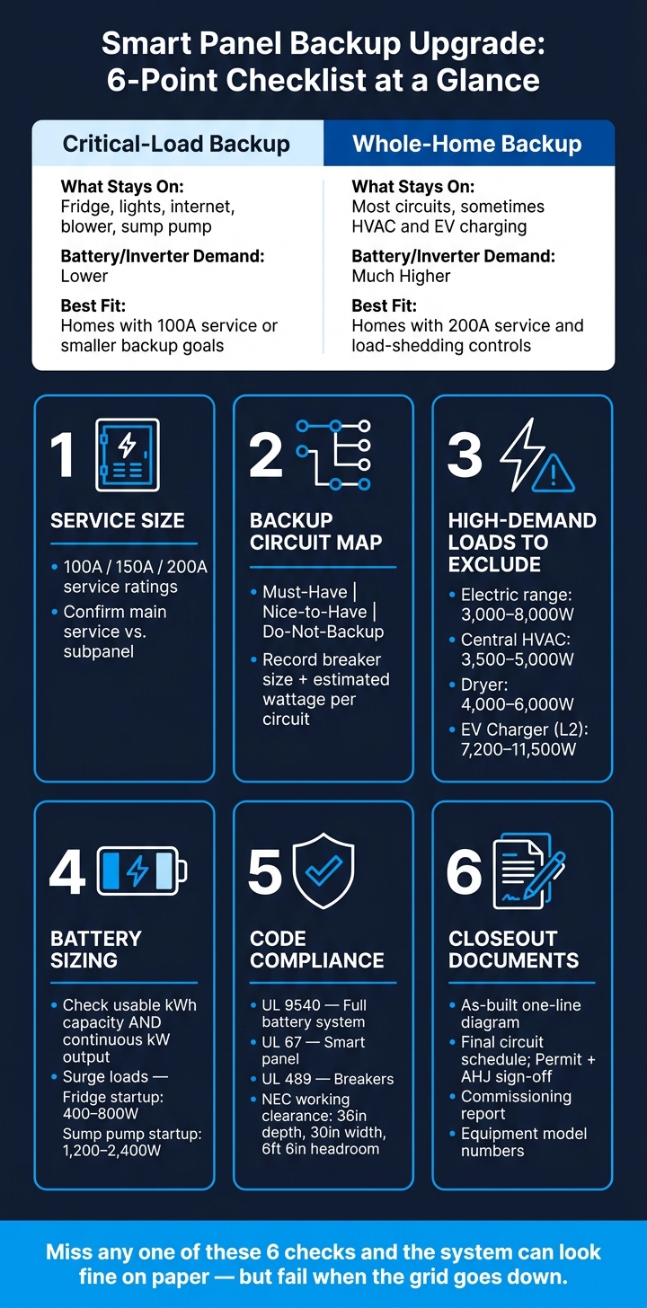
Smart Panel Backup: Critical-Load vs. Whole-Home Backup Comparison
PART 01: Replacing my subpanel to install EcoFlow Smart Home Panel 3 & Delta Pro Ultra X!
sbb-itb-501186b
Quick comparison
| Backup choice | What I’d keep on | Battery/inverter demand | Best fit |
|---|---|---|---|
| Critical-load backup | Fridge, lights, internet, blower, sump pump | Lower | Homes with 100 A service or smaller backup goals |
| Whole-home backup | Most circuits, sometimes HVAC and EV charging | Much higher | Homes with 200 A service and load-shedding controls |
So before I buy a panel, inverter, or battery, I’d use this checklist to make sure the design, install space, and outage plan all line up.
Pre-Buy Checklist: Service Size, Backup Loads, and Hardware Fit
Verify Service Size and Choose a Backup Strategy
Once you know what the backup system needs to cover, the next step is simple: make sure the home's electrical setup can handle the gear.
Check the service rating, main breaker size, open breaker spaces, and whether the home uses 120/240 V split-phase, which is standard for most U.S. homes. You also need to confirm whether the panel is the main service equipment or a subpanel fed from it. That detail matters because it can change whether you need a backup gateway or other transfer equipment.
It also helps to note the feeder size and whether the home may need a service upgrade before any backup hardware goes in. A battery setup can look great on paper, then hit a wall once you see what the panel can actually support.
After that, map the loads that will stay on during an outage.
Exclude High-Demand Loads and Size the Battery Correctly
Start by listing every circuit. Then sort each one into three buckets:
- Must-have
- Nice-to-have
- Do-not-backup
For each circuit, record the breaker size, estimated wattage, and backup priority. This makes the plan much easier to build and much easier to price.
Some loads usually land in the do-not-backup group because they draw too much power. Common examples include electric ranges (3,000–8,000 W), central HVAC (3,500–5,000 W for a 3-ton unit), electric dryers (4,000–6,000 W), electric water heaters, and Level 2 EV chargers (7,200–11,500 W).
Battery sizing isn't just about capacity. You need to check both:
- Usable capacity in kWh
- Continuous output in kW
Surge ratings matter too. Refrigerators, sump pumps, and well pumps can pull a short startup surge that's much higher than their normal running load. If you skip that detail, a system can look big enough but still struggle when key appliances kick on.
Check Compatibility, Space, and Room for Future Expansion
Before ordering anything, confirm the exact hardware set and make sure the install space works in the real world, not just in a spec sheet.
The smart panel, gateway or transfer equipment, inverter, and battery should all be approved by the manufacturer to work together. Check the manufacturer's documentation for the exact compatible equipment set, firmware requirements, app-control limits, and any rules about mixing brands.
Then measure the space. Look at wall area, mounting height, conduit paths, and nearby obstructions. Also confirm the install can meet NEC working-clearance rules: at least 36 inches of depth, 30 inches of width, and 6 feet 6 inches of headroom in front of electrical equipment.
It's also smart to leave space for later additions, like another battery module, a future subpanel, or solar. A setup installed right at its limit on day one doesn't leave much room to grow.
That review leads straight into the code and permit check before installation.
Pre-Install Checklist: Electrical Design and Code Review
This step checks the design against code before installation starts. It confirms that load shedding, disconnects, and overcurrent protection are set up for outage operation. It also helps lock in the final backup layout before circuit mapping begins.
Confirm Listings, Disconnects, and Conductor Sizing
The battery system must be listed to UL 9540 as a complete system. That means the inverter, controls, and protection are reviewed together as one unit. The smart panel must be listed to UL 67, and breakers must be listed to UL 489. They also need markings that match the planned use, including ESS and backfeed use.
NEC 706 calls for a dedicated ESS disconnect that opens all ungrounded conductors. It must be readily accessible and within sight of the battery enclosure, or lockable open if it is not. It must be plainly marked ENERGY STORAGE SYSTEM DISCONNECT and must clearly show open and closed position. If the system includes solar, a separate PV disconnect is also required under NEC 690 and NEC 705.
For conductor sizing, follow this order:
- Size the OCPD at 125% of maximum discharge current
- Then size conductors to match the OCPD under NEC 310
Use THHN/THWN-2 conductors. Base ampacity on 75 °C terminal ratings unless the equipment says otherwise. If ambient temperature is above 86 °F (30 °C), or if more than three current-carrying conductors are in the same conduit, apply the needed derating factors.
Review Labeling, Fault Current, and Site Conditions
The service panel needs a placard that identifies all power sources and disconnect points. The ESS disconnect should be labeled with nominal voltage, maximum DC voltage, available fault current from the ESS, and an arc-flash label where required. In the backed-up panel, the circuit directory should clearly show which loads are on backup and which are not. Good labeling makes shutdown and load-shedding calls much easier during an outage.
Available fault current must be calculated - or obtained from the utility - at the service entrance and at each downstream panel. Every breaker and disconnect must have an interrupting rating that meets or exceeds the available fault current at that location. Standard residential breakers are often rated at 10 kAIC, so if calculated fault current is higher than that, you may need higher-rated equipment.
Build a Permit and Inspection Checklist
Build this table during design, then update it in the field.
| Requirement | Code Reference | Design Decision | Verified Status |
|---|---|---|---|
| ESS listed to UL 9540 as a complete system | NEC 110.3(B), NEC 706 | Confirm UL 9540 listing on spec sheet | Design: ☐ Field: ☐ |
| ESS disconnecting means, readily accessible | NEC 706.7 | Install the disconnect adjacent to the battery cabinet | Design: ☐ Field: ☐ |
| Disconnect marked ENERGY STORAGE SYSTEM DISCONNECT | NEC 706.11 | Engraved placard with voltage and fault current | Design: ☐ Field: ☐ |
| Conductor ampacity meets or exceeds OCPD rating, with derating | NEC 310, NEC 240 | Size per ESS max output × 125%; apply temperature derating | Design: ☐ Field: ☐ |
| Breaker AIC meets or exceeds available fault current | NEC 110.9, 110.10 | Obtain utility fault current data; select rated breakers | Design: ☐ Field: ☐ |
| Service placard listing all sources and disconnect points | NEC 705.10, 706.11 | Install engraved placard at main panel | Design: ☐ Field: ☐ |
| Clearances and access maintained | NEC 110.26, 706.10 | Confirm adequate access in site photos | Design: ☐ Field: ☐ |
| Installation per manufacturer instructions | NEC 110.3(B) | Manuals on-site; torque specs documented | Design: ☐ Field: ☐ |
Inspectors will usually want to see approved plans, open ESS disconnects, and all labels in place before dead-front removal. Once this review is clean, move to circuit labeling and battery pairing.
Circuit Mapping and Battery Pairing Checklist
Label Every Circuit Before Moving Loads
Start with the circuits already marked for backup in the design review. Before you move anything, label every breaker with a clear, specific description. NEC 408.4(A) says each circuit needs a permanent label that accurately identifies its function and location. A simple format like Room – load – detail works well: Kitchen – GFCI receptacles – north wall or Mechanical – Sump pump – primary.
Go through the panel one breaker at a time. Shut it off, confirm what it serves, and write it down. Record:
- Breaker position
- Amperage
- Whether it is single-pole or double-pole
- A specific circuit description
For 240 V dedicated appliances like ranges, dryers, and heat pumps, mark them as 240 V – dedicated appliance. That helps you avoid moving only one part of a multi-wire circuit into the backup group by mistake. Keep a printed schedule in the panel and save a digital copy for handoff. The panel labels should also match what appears in the app.
Assign Backup Priority and Load-Shedding Rules
Once the circuit list is labeled, use it to set backup behavior. Put each circuit into one of three tiers and give it a numeric priority. Those priorities control automatic shedding during an outage.
| Priority Tier | Typical Circuits | Shedding Behavior |
|---|---|---|
| Must Have (Critical) | Refrigerator, sump pump, router/modem, furnace controls, medical equipment, essential lighting near exits and stairs | Stays on until battery hits reserve |
| Optional | Living room receptacles, bedroom lighting, microwave circuit, garage door opener, some HVAC or comfort loads | Shed when battery drops to a lower state of charge |
| Off | Electric dryer, EV charger, electric resistance heat, pool pump, workshop receptacles | Off for the entire outage |
Assign 1, 2, or 3 to each circuit, then map those priorities to the panel’s load-shedding settings.
Match Circuit Demand to Battery Output and Surge Limits
After priorities are set, check each backed-up circuit against both continuous output and surge output. The most common battery-pairing mistake is skipping startup surge.
A refrigerator usually draws about 100–200 W while running and 400–800 W at startup. A sump pump often draws about 400–1,200 W while running and 1,200–2,400 W at startup. On paper, the running load may look fine. But if the refrigerator and sump pump kick on at the same time, that combined surge can push past the inverter’s peak output rating.
Build a circuit demand table and compare every backed-up circuit to the battery’s continuous and surge ratings before you lock in the layout:
| Circuit Name | Breaker Size | Continuous Load | Surge Load | Backup? | Priority |
|---|---|---|---|---|---|
| Kitchen – Refrigerator | 15 A | ~150 W | ~600–800 W | Yes | Must Have |
| Mechanical – Sump pump | 20 A | ~500 W | ~1,500–2,400 W | Yes | Must Have |
| Office – Router/modem | 15 A | ~10–25 W | Negligible | Yes | Must Have |
Add up the continuous wattage of all backed-up circuits and make sure it stays below the battery’s rated continuous output. Then check the worst-case surge combinations, like the refrigerator and sump pump starting together, and confirm that the battery’s peak output can cover them. If it can’t, take a load out of backup or change the load-shedding rules so those starts do not overlap. Keep this table on hand during commissioning and handoff.
Installer Verification and Final Handoff
Questions to Ask Before Installation Begins
Once the load map is set, check the installer's assumptions before any equipment gets ordered. At this stage, get three things confirmed in writing: the load calculation, the transfer method, and how backup and recharging work.
Ask for a written circuit load calculation that shows running watts, duty cycles, and daily kWh for every backed-up load. That number should come from your own usage data and past utility bills, not a generic template.
You should also ask how the system transfers during an outage. Does it switch over without interruption, or is there a brief drop? And if the grid is down, can the solar setup recharge the battery?
Also verify that the installer is licensed in your state, has done a load calculation under NEC Article 220, and is using major components with a listing from UL, ETL, or CSA. That includes the smart panel, battery, and transfer equipment.
Commissioning Tests and Required Project Documents
Even after the design is approved, the system still needs a live test before handoff. Run an outage test and make sure the setup behaves the way the plan says it should. Backup circuits should stay on. Non-backup circuits should shut off. Load shedding should trigger at the right time. And the app should match what the panel is doing in the field.
Go through the app with the installer as well. Check circuit names, priority tiers, fault messages, and support contacts. The app names should match the final circuit schedule exactly.
At handoff, collect the full document package in one place. If you ever need maintenance, an inspection, or a part swap, this paperwork saves time and headaches.
| Document | What It Covers |
|---|---|
| One-line diagram (as-built) | Service, smart panel, battery, inverter, disconnects, interconnection point |
| Final circuit schedule | Every breaker: load description, backup status, priority tier |
| Permit set + AHJ inspection sign-off | Electrical permit and final approval from the Authority Having Jurisdiction |
| Equipment list with model numbers | Panel, battery, inverter, breakers, disconnects, sensors |
| Commissioning report | Test results: outage simulation, load shedding, app configuration |
| O&M guide | Maintenance intervals, fault thresholds, when to call a professional |
For breakers or other parts that may need to be replaced later, exact model numbers and compatibility notes make sourcing much easier. Any replacement still has to meet the original listing rules and the manufacturer's compatibility guidance before installation.
With the paperwork in hand, only final inspection and turnover remain.
Conclusion: The Minimum Checklist Before You Buy or Install
The job is only done when the load map, outage behavior, and project documents all line up with the design. Before you sign off, confirm these six must-check items:
- Service size
- Backup circuit map
- Labels
- Battery capacity and surge limits
- Code compliance and listings
- Complete turnover package
FAQs
Do I need whole-home or critical-load backup?
Not necessarily. For many facilities, it makes more sense to back up critical loads instead of the entire home. The right setup depends on how the site operates and how much risk you’re willing to accept.
Critical loads are the systems that can’t afford to go down. If they fail, you may face immediate data loss, safety issues, or major downtime. That’s the stuff you protect first.
A walkthrough helps sort critical equipment from non-critical equipment. That way, you don’t spend extra money backing up loads that aren’t needed during an outage. It also helps preserve battery runtime instead of draining it on discretionary loads.
How do I know if my battery can handle surge loads?
Add up the running watts for every piece of equipment connected to the system. Then take the single highest starting wattage and add that on top. Next, compare the total to the battery’s maximum discharge power rating in kW.
If the battery’s maximum discharge power meets or beats that surge demand, it should be able to handle the load. For extra peace of mind, add a 25% safety margin.
What documents should I get at project handoff?
At project handoff, ask for a complete turnover package for maintenance and compliance.
That package should include:
- Approved one-line diagrams, as-built drawings, and equipment data sheets
- Startup and commissioning reports, including FAT/SAT documentation
- BMS or EMS configuration files and protection relay settings
- O&M manuals, software licenses, fuel test records, and a signed certificate of completion





