




International Seismic Standards for Cable Management
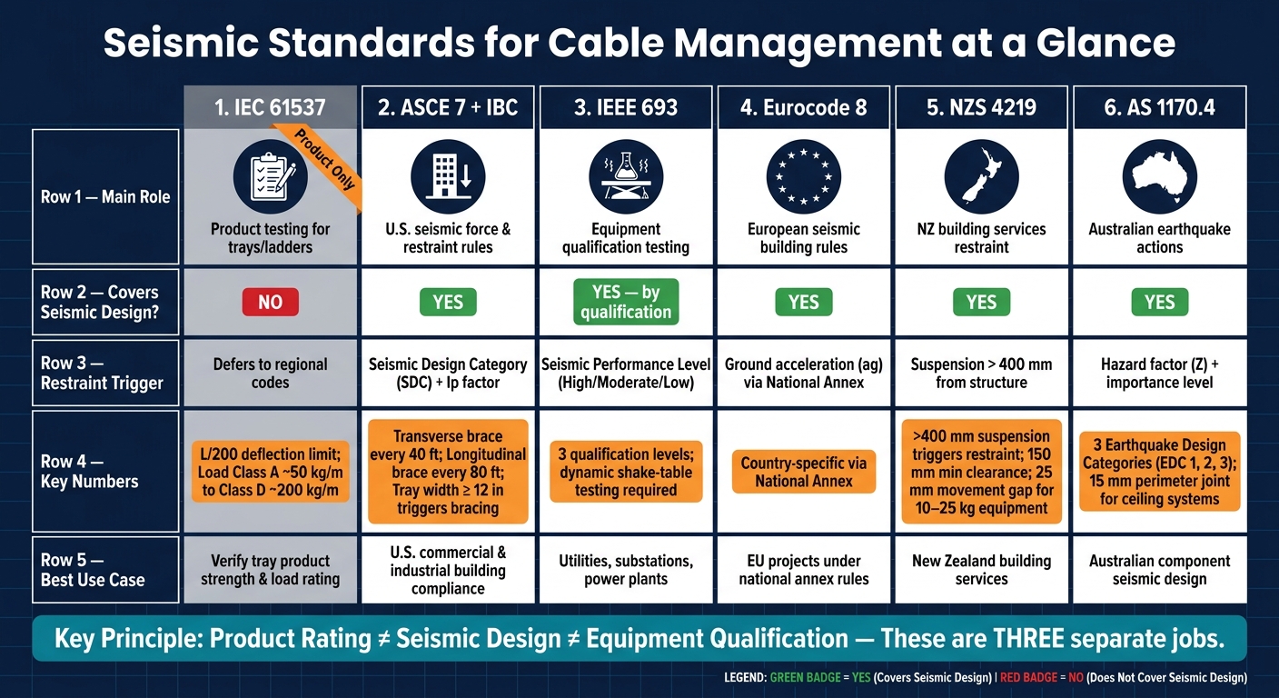
If you’re working on a U.S. project, one fact matters most: an IEC 61537 tray rating does not, by itself, meet seismic code. You still need a regional seismic code to size braces, check anchors, and confirm spacing.
I’d boil the article down like this:
- IEC 61537 checks the tray or ladder product itself, mainly by SWL and deflection testing.
- ASCE 7 + IBC set the U.S. seismic restraint rules for cable trays, conduits, bus duct, hangers, and anchors.
- IEEE 693 is for test-qualified utility and substation assemblies, often through shake-table testing.
- Eurocode 8, NZS 4219, and AS 1170.4 are regional design frameworks used outside the U.S.
- The biggest split is simple: product rating, project seismic design, and equipment qualification are three different jobs.
A few numbers stand out right away:
- In U.S. work, cable tray bracing often starts at 12 inches tray width.
- Typical ASCE 7 spacing is 40 ft transverse and 80 ft longitudinal.
- NZS 4219 calls for restraint when trays are suspended more than 400 mm from structure.
- IEC 61537 uses a midspan deflection limit of L/200 under working load.
If I were screening submittals, I’d ask one question first: Does the package show both tray strength and seismic restraint compliance for the jobsite? If not, it’s incomplete.
Seismic Standards for Cable Management: IEC 61537 vs ASCE 7 vs IEEE 693 & More
Quick Comparison
| Standard | Main Role | Covers Seismic Design? | Best Use |
|---|---|---|---|
| IEC 61537 | Product testing for trays/ladders | No | Check tray strength and load rating |
| ASCE 7 + IBC | U.S. force and restraint rules | Yes | U.S. building compliance |
| IEEE 693 | Equipment qualification testing | Yes, by qualification | Utilities, substations, power sites |
| Eurocode 8 | European building seismic rules | Yes | Projects under EU national annex rules |
| NZS 4219 | NZ restraint rules for building services | Yes | New Zealand building services |
| AS 1170.4 | Australian earthquake actions | Yes | Australia-based component design |
So the short answer is this: don’t approve cable management seismic compliance based on a product label alone. Check the governing code, the brace layout, the anchor details, and the installation rules before the buy goes through.
sbb-itb-501186b
1. IEC 61537
Scope
IEC 61537:2023 is the main international standard for cable tray and ladder systems. It focuses on product performance, mechanical strength, and Safe Working Load (SWL).
It applies to metallic and nonmetallic cable tray and ladder systems used to support cables in electrical and communications installations. In plain terms, IEC 61537 is a product standard, not a seismic design rule. It does not cover conduit systems or cable trunking.
The 2023 edition is the third edition and a major revision. It expanded from 161 pages in the 2006 edition to more than 300 pages. It also added revised corrosion classifications, updated SWL test procedures, and new tests for support devices such as cantilevers, pendants, C-shape ceiling supports, and trapeze systems.
Analysis Approach
IEC 61537 is built around test-based verification. Manufacturers set a Safe Working Load (SWL), stated in Newtons, at a given support distance. Midspan deflection must remain within L/200 under working load. For a 10-foot span, that means no more than 0.6 inch of deflection.
The standard also sets load classes from Class A, at about 50 kg/m, to Class D, at about 200 kg/m. These ratings help answer a simple question: what can the tray carry? Seismic codes deal with a different question: how must it be restrained?
Support and Bracing Rules
IEC 61537 stops at product performance. Seismic bracing comes from regional codes. Once tray capacity is checked, the bracing design has to follow the governing structural code. For U.S. projects, ASCE 7-22 and the IBC control bracing design after the tray’s mechanical capacity has been verified through IEC 61537 data.
A practical way to handle this is simple:
- Use IEC 61537 to confirm tray capacity
- Use ASCE 7 to determine brace layout and restraint needs
- Request SWL test reports, load/deflection tables, and installation drawings that show support spacing before you specify the system
Use IEC 61537 to confirm capacity; use regional codes to complete the seismic design.
2. ASCE 7 with IBC
Scope
ASCE 7-22, as adopted by the IBC, sets the U.S. rules for seismic loads and restraint for nonstructural components attached to the structure. That includes cable trays, conduit, bus duct, hangers, trapezes, and their anchors.
Here’s the clean way to think about it: ASCE 7 handles loads and restraint design. IEC 61537 handles product strength. In practice, IEC 61537 tells you whether the tray itself has been verified for strength, while ASCE 7 tells you what seismic forces the system has to resist and how the restraint should be laid out.
Restraint Triggers
Not every installation needs seismic bracing. ASCE 7 looks at the building’s Seismic Design Category (SDC) and the Component Importance Factor ($I_p$) to decide when bracing is required.
ASCE 7 bracing triggers and spacing are shown below.
| Component Type | When bracing is required | Transverse Spacing | Longitudinal Spacing |
|---|---|---|---|
| Cable Tray | Width ≥ 12 inches | 40 ft | 80 ft |
| Conduit (Trapeze) | Weight > 10 lb/ft | 40 ft | 80 ft |
| Bus Duct | Always required | 40 ft | 80 ft |
| Critical Systems ($I_p$ = 1.5) | Emergency power, smoke control, or Risk Category IV structures such as hospitals and emergency operations centers | Project-specific | Project-specific |
Check $I_p$ early. Emergency power, smoke control, and Risk Category IV components use $I_p = 1.5$. That matters because essential systems face tighter bracing thresholds, and $I_p = 1.5$ increases seismic demand.
Analysis Approach
ASCE 7 calculates $F_p$ from site seismic demand, component weight, and elevation. Components installed on upper floors are hit with higher demand, and roof-level $H_f$ can be greater than 2.5.
Support and Bracing Rules
Use vertical hangers for dead load and diagonal braces for lateral and longitudinal seismic restraint. Transverse braces are required every 40 ft, longitudinal braces every 80 ft, and extra braces must be placed within 24 inches of any elbow or branch turn.
One mistake shows up all the time: bracing in only one direction. That’s not enough. Both axes of motion must be restrained.
For Seismic Design Categories C–F, post-installed anchors must be sized with $\Omega_0$, and adhesive anchors must be qualified to ACI 355.4 and ACI 318-19.
These rules set the U.S. baseline for comparing how other standards deal with component restraint and anchorage.
3. IEEE 693
Scope
Once ASCE 7 sets the design forces, IEEE 693 steps in when a utility wants test-qualified seismic performance. IEEE 693 is a seismic qualification standard for substation equipment and supports.
For cable management, this matters when trays, ladders, or support assemblies are called out as part of a qualified substation package, not as a standalone tray rule. It applies to new substations and major upgrades, not retrofits of existing substations.
Analysis Approach
ASCE 7 sets the seismic demand. IEEE 693, on the other hand, qualifies equipment through testing.
That’s the big difference. ASCE 7 leans on a force-based bracing method, while IEEE 693 uses qualification levels - High, Moderate, or Low - and checks performance through qualification testing.
Two testing methods are used:
- Dynamic testing: Shake-table testing under earthquake motion.
- Static testing: Load testing without motion.
If the assembly doesn’t pass qualification, the frame, bracing, or materials need to be revised and tested again.
Support and Bracing Rules
IEEE 693 treats cable management as part of the full qualified equipment setup, not as a separate item on its own. Its qualification documents spell out the structural capacities, performance requirements, and installation methods for the qualified configuration.
"This recommended practice is designed as an integrated set of requirements for the seismic qualification of electrical power equipment. This recommended practice is to be applied without modification or removal of any requirement, except as allowed herein." - IEEE SA
Procurement documents should state the qualification level and the installation configuration.
4. Eurocode 8 (EN 1998)
Scope
Eurocode 8 covers the seismic design and construction of buildings and civil engineering works in seismic regions. Its goals are to protect human life, limit damage, and keep critical facilities running after an earthquake.
For cable management, EN 1998-1:2004 is the main reference. In that framework, cable trays and ladders are treated as non-structural elements. Put simply, Eurocode 8 sets the seismic design rules, while BS EN 61537 applies to the tray product itself.
Restraint Triggers
Unlike the fixed thresholds used in the U.S., Eurocode 8 works country by country. Each jurisdiction sets its own protection levels through a National Annex, so the trigger for seismic bracing depends on where the project is located. That’s the big shift here: there isn’t one single trigger that applies everywhere.
Systems tied to civil protection, such as emergency power feeds in hospitals, fall into a higher importance category. That means tighter performance demands and a stronger need to stay in service after a seismic event. In practice, the applicable National Annex is what you use to set bracing intervals.
Analysis Approach
Eurocode 8 follows a performance-based approach. Seismic demand comes from the National Annex and the local ground acceleration. As a result, support spacing is set project by project. It should follow the National Annex and site acceleration, not the tray load class.
Support and Bracing Rules
For product verification, use BS EN 61537. For seismic layout, use the National Annex. Cable trays and ladders used in Eurocode 8 designs should comply with BS EN 61537, the European harmonized version of IEC 61537, which covers manufacturing and load testing. Channel support systems used with these designs should meet BS 6946.
There’s also a practical detail that matters on site. Thermal cycling can loosen anchors over time, so use lock nuts or spring washers on anchor bolts and beam clamps to help reduce loosening.
5. NZS 4219
Scope
Where Eurocode 8 leans hard on national annexes, NZS 4219 is more direct about when cable management needs seismic restraint. NZS 4219:2009 is New Zealand’s standard for seismic restraint of building services, including cable trays, conduits, ducting, pipework, and suspended ceilings.
Restraint Triggers
Cable trays suspended more than 400 mm from their structural support must be seismically restrained. If restraint isn’t required, the tray still needs at least 150 mm of clearance from hangers and braces so parts don’t hit each other during shaking. That clearance rule comes from hard lessons in the Canterbury earthquakes, where poor clearance and stiffness mismatches played a big part in the damage.
Equipment over 25 kg needs a project-specific restraint design. Equipment from 10 to 25 kg must be independently supported and have a 25 mm movement gap. Cables entering a building must be sleeved to allow 25 mm of movement in all directions.
Analysis Approach
NZS 4219 works alongside NZS 1170.5:2004 to set the design seismic actions for non-structural systems. In practice, compliance usually follows one of two paths:
- a Building Code-approved proprietary system
- a Specific Engineering Design (SED) by a Chartered Professional Engineer (CPEng)
It’s not enough to sort this out on drawings alone. Clearances and flexible joints need to be checked in the field as well.
Those project-specific design paths turn into strict site rules for clearance, support, and movement.
Support and Bracing Rules
Use flexible connections across seismic gaps and at building interfaces. Electrical cabinets must have doors with top and bottom catches, and internal components must be positively restrained with straps, bars, or bolts. Pipes and conduits under 50 mm, or runs rigidly supported within 150 mm of the structure above, usually don’t need added seismic design.
"Significant damage during the Canterbury earthquakes was caused by non-structural elements such as ceilings and in-ceiling services clashing. This was caused by insufficient clearance and/or stiffness incompatibilities." - MBIE Practice Advisory 19
That quote gets to the point. Even when the main structure performs as intended, service clashes can still cause a mess.
Early coordination between the design coordinator, structural engineers, and building services engineers is critical to avoid conflicting specifications.
6. AS 1170.4
Scope
In Australia, AS 1170.4 sets the rules for earthquake actions for building components, including cable distribution systems. These systems are directly covered under the standard’s non-structural component requirements. Compared with NZS 4219, AS 1170.4 leans more on engineering analysis than on fixed clearance rules.
Analysis Approach
For cable management, the main issue isn’t only anchorage. It’s also how the system reacts to floor acceleration and drift. Australia uses three Earthquake Design Categories:
- EDC 1 for simple static checks
- EDC 2 for multi-directional static analysis
- EDC 3 for dynamic analysis on higher-risk or taller structures
Engineers supply floor acceleration and drift limits, and manufacturers use those values to check whether the system matches site demands.
Support and Bracing Rules
Those design values then shape the restraint layout, anchor choice, and movement allowance. A common approach is to use one fixed restraint point and sliding supports at other locations so the system can move with drift.
For ceiling-integrated cable systems, a 15 mm perimeter joint is recommended in some ceiling designs to allow for movement.
Side-by-Side Comparison of Seismic Requirements
The main differences come down to scope, what triggers restraint, and how systems are checked.
This table sums up the day-to-day differences across the main standards:
| Standard | Cable Management Scope | Restraint Trigger | Analysis Approach | Units |
|---|---|---|---|---|
| IEC 61537 | Yes - trays/ladders only | Defers to regional codes | Static (SWL testing) | Metric |
| ASCE 7 / IBC | Yes - through NEC installation rules | Seismic Design Category (SDC) | Force-based | U.S. customary |
| IEEE 693 | Yes - equipment supports | Seismic Performance Level | Dynamic shake-table qualification | Metric and U.S. customary |
| Eurocode 8 | Yes - non-structural components | Ground acceleration (a_g) | Static and dynamic | Metric |
| NZS 4219 | Yes - non-structural components | Component importance / zone | Static and dynamic | Metric |
| AS 1170.4 | Yes - non-structural components | Hazard factor (Z) / importance | Static, with dynamic analysis in higher EDCs | Metric |
One point stands out right away: IEEE 693 is the only standard here that is built around direct qualification testing for vibration resistance. That makes it a different beast. Instead of leaning mostly on design calculations, it uses dynamic shake-table qualification to show that equipment supports can perform under seismic motion.
The other standards tend to rely on project engineering to set damping assumptions and work through the math. So while they still deal with seismic restraint, they don't center the process on direct vibration qualification in the same way.
IEC 61537 also has its own lane. It includes impact resistance testing up to 20 J to simulate mechanical stress. That's useful, but it's not the same thing as a full seismic vibration qualification path.
Those gaps matter when you're weighing tradeoffs, comparing systems, or trying to figure out what to buy from one market versus another.
Pros, Cons, and Sourcing Notes for U.S. Projects
Use the table below to line up each standard with the job in front of you. After the technical comparison, the buying call usually comes down to three things: code fit, test burden, and submittal quality.
| Standard | Strengths for U.S. Projects | Limitations | Best-Fit Project Types |
|---|---|---|---|
| ASCE 7 / IBC | U.S. code baseline | Complex calculations; requires site-specific soil and occupancy data | U.S. commercial and industrial buildings |
| IEEE 693 | Used by utilities for equipment qualification; bridges ASCE 7 and electrical infrastructure | High testing cost; primarily scoped to substations and power equipment; is usually too costly for standard commercial builds | High-voltage substations, utility infrastructure, power plants |
| IEC 61537 | Rigorous mechanical testing; 2023 edition expanded SWL test procedures | Not a seismic standard; excludes conduit systems; does not satisfy U.S. code compliance by itself | International projects or imported equipment |
| Eurocode 8 | Comprehensive for structural building elements | Relies on ductility and inelastic behavior, which can be a poor fit for brittle electrical components like cast-aluminum enclosures | General building structures in Europe |
| NZS 4219 / AS 1170.4 | Regionally specific for Oceania seismic conditions | Not recognized for U.S. domestic code compliance | Projects located in New Zealand or Australia |
IEEE 693 is the strongest path for utility-grade qualification. But for a standard building job, the testing load and cost often make it hard to justify.
That shifts attention to submittals. If you're buying imported IEC equipment, ask for SWL data at the project span and check that the submitted load rating matches the required U.S. class. A label alone doesn't tell you enough.
Before purchase, request:
- shake-table reports
- resonant-frequency results
- pre- and post-test functional checks
- stamped brace details
- anchor approvals
Under IBC Chapter 17, special inspections may be required for anchor installations in Seismic Design Categories C through F. So anchor compatibility isn't just a purchasing detail. It's a code issue.
And that's where many teams get tripped up: the anchor-to-structure connection. Under ASCE 7-22, transverse braces are typically required every 40 feet and longitudinal braces every 80 feet. If you buy through Electrical Trader, require the same submittal package before ordering.
Use the governing code - not the product label - as the final approval test.
Conclusion
These standards split into three separate jobs: product performance, seismic design, and qualification testing. IEC 61537 deals with tray product performance. ASCE 7 and the IBC set U.S. seismic loads and restraint rules. IEEE 693 covers qualification testing for substation equipment. On its own, none of them gives you a complete compliance path.
For U.S. projects, a tray certified to IEC 61537 does not automatically meet bracing rules. You need to confirm the Seismic Design Category, set the correct Importance Factor (Ip), and make sure the procurement package clearly separates the tray body from its support and anchorage hardware. In plain English: tray certification and support/anchorage approval are two different things, and procurement needs to treat them that way.
Handle the standards early, and procurement and installation stay in sync.
FAQs
Why isn’t IEC 61537 enough for U.S. seismic compliance?
IEC 61537 covers product performance, including safe working load and corrosion resistance. But it does not cover the seismic installation rules required in the United States.
In the U.S., seismic compliance for cable management systems is governed by the International Building Code and ASCE 7-22. These codes set the design, bracing, and anchorage criteria based on the seismic design category.
So while IEC 61537 points to local structural codes for seismic bracing details, it isn't enough on its own for U.S. projects.
How do I know if my cable tray needs seismic bracing?
In the United States, ASCE 7-22 sets the rules for whether a cable tray needs seismic bracing.
Under Section 13.6.7, bracing is required for cable trays that are 12 in. wide or more. The need for bracing can also depend on the tray’s fill ratio.
For trapeze-supported systems, bracing is required when the combined weight of the trapeze and cables is more than 10 lb/ft.
Always confirm project-specific bracing intervals and design requirements with local codes or a licensed engineer.
What should a complete seismic submittal include?
A complete seismic submittal for cable management systems should show code compliance by naming the governing standards, such as IBC 2018 or ASCE 7-22, and by including load calculations for component weights and expected seismic forces.
It should also include certified test reports or analysis, along with installation details for bracing layouts, anchorage, and support connections. Those details help confirm compliance with local seismic design categories and importance factors.





