
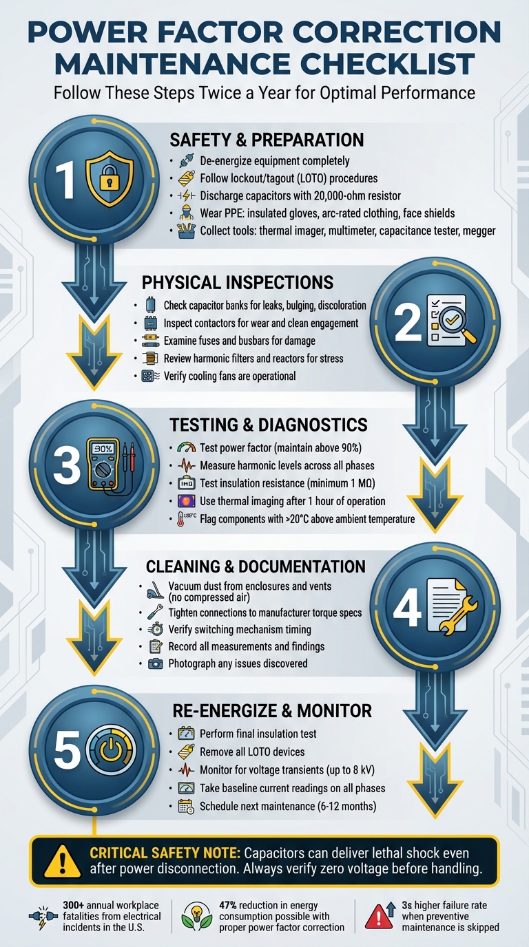
Power Factor Correction Maintenance Checklist
Power factor correction systems help reduce energy costs and improve electrical efficiency, but they require regular maintenance to stay effective.
Neglecting these systems can lead to failures, costly downtime, and even safety hazards. This checklist simplifies the maintenance process, covering safety steps, inspections, testing, and cleaning to ensure your system operates reliably.
Key Steps:
- Safety First: De-energize equipment, follow lockout/tagout (LOTO) procedures, and discharge capacitors properly.
- Inspect Components: Check capacitor banks for leaks, loose connections, and overheating. Examine contactors, fuses, and busbars for wear or damage.
- Test and Diagnose: Measure power factor, harmonic levels, and insulation resistance. Use thermal imaging to detect hot spots.
- Clean and Document: Vacuum dust, tighten connections, and maintain detailed records of findings and repairs.
- Re-Energize and Monitor: Confirm system stability, take baseline readings, and schedule the next maintenance cycle.
By following these steps twice a year, you can prevent breakdowns, avoid penalties, and keep your system running efficiently.
Power Factor Correction System Maintenance Checklist: 5-Step Process
Maintenance of Power Factor Correction equipment | COMAR Condensatori (English sub)
Safety and Preparation Steps
Before diving into work on your power factor correction (PFC) system, it’s critical to establish an electrically safe environment. This means completely de-energizing the equipment and strictly following lockout/tagout (LOTO) protocols. Electrical hazards are no small matter - each year, over 300 workplace fatalities and 4,000 injuries in the U.S. are linked to electrical incidents.
Follow Safety Procedures
Capacitors can be particularly dangerous because they store electrical energy even after the power is turned off. Bennie Kennedy from Fluke emphasizes this point:
Capacitors are energy storage devices that can deliver a lethal shock long after the power to them is disconnected.
Once you’ve de-energized the system, wait for the manufacturer-specified discharge time. Use a 1,000V-rated DC meter to confirm de-energization by checking phase-to-phase and phase-to-ground. Afterward, discharge capacitors with a 20,000-ohm resistor to ensure they’re safe to handle.
Develop a detailed job safety plan and hold a pre-task briefing to address concerns about the procedure, personnel safety, and qualifications. Christopher Coache, NFPA Senior Electrical Engineer, highlights the importance of these briefings:
The briefing also gives employees the opportunity to express any concerns they have about the task, the procedure, their qualifications, or their safety.
One critical safety rule: never open a current transformer (CT) secondary circuit while the system is under load. This can create lethal voltage across the CT terminals. Always short-circuit CT secondaries to ground before working on control circuits.
Personal protective equipment (PPE) is another must. Follow NFPA 70E guidelines, which recommend insulated gloves, flame-resistant arc-rated clothing, and face shields. Ensure all equipment displays proper arc flash labels with details on incident energy, boundaries, and required PPE.
Collect Required Tools
Having the right tools on hand is essential for both safety and efficiency. Here’s what you’ll need:
- Thermal imager: Identifies overheating components without direct contact.
- Digital multimeter with a current clamp: Measures voltage and current.
- Capacitance tester: Ensures capacitors are within 10% of their rated value.
- Insulation resistance tester (megger): Checks continuity and insulation integrity.
- Power quality analyzer: Measures power factor and monitors harmonic levels.
Additional must-haves include a complete LOTO kit, a discharge resistor, and a high-voltage detector (commonly called a "glowstick") to confirm circuits are dead. Maintenance supplies should also include an industrial vacuum for cleaning (avoid using compressed air), a torque wrench for proper connection tightening, and lint-free rags paired with approved cleaning solvents. Ensure all tools are either double-insulated or properly grounded.
Plan Maintenance Schedule
To keep your PFC system running smoothly, manufacturers generally advise inspections twice a year. However, factors like system age, load patterns, and environmental conditions may require adjustments to this schedule. Systems exposed to frequent switching, heavy loads, or harsh environments often need more frequent checks.
Organize maintenance into tiers for better efficiency:
- Daily visual inspections: Look for hazards like exposed wires or signs of overheating.
- Weekly operational checks: Record voltage and current readings.
- Annual detailed testing: Use thermal imaging and conduct a thorough system analysis.
Thermal imaging is particularly useful for spotting issues like loose connections or failing components. Perform this on an energized system for at least one hour before a scheduled shutdown. Remember, skipping preventive maintenance can triple the failure rate of equipment components.
Physical Component Inspections
After ensuring your system is safely de-energized and all preparatory steps are complete, it’s time to inspect the physical components. This step is crucial for confirming hardware integrity and catching potential issues early. Carefully examine each part to spot signs of wear or degradation.
Check Capacitor Banks
Begin by inspecting the capacitor banks for visible issues. Look for bulging, leaking dielectric fluid, or discoloration on the casing - these are clear indicators of serious problems that demand immediate attention.
Next, check the terminal connections. If the temperature readings exceed 20°C above the surrounding ambient temperature, it signals excessive resistance. Additionally, heating or moisture around the terminals points to potential failures. Bennie Kennedy from Fluke highlights the risks of overlooking these problems:
Problems such as loose connections, blown fuses or failing capacitors can reduce the amount of power correction available and, in extreme cases, even cause a total system failure or a fire.
Use thermal imaging to check for blown fuses. A failed capacitor will generally appear cooler than its functioning counterparts in the same stage, while loose connections show up as hot spots. If you discover a blown fuse, shut down the capacitor bank immediately to investigate the root cause. The issue could stem from a bad capacitor, a reactor problem, or faulty fuse clips.
Inspect Contactors, Fuses, and Busbars
Pay close attention to the contactors. Check for wear, unusual switching noises, and ensure they engage cleanly without signs of welding. Discoloration or moisture on these components often signals overheating or environmental stress that needs to be addressed.
Examine the tightness of all terminals and busbar connections. Loose connections generate resistance, which leads to heat buildup and can cause more significant failures. Use a thermal imager to scan busbars for hot spots, as these may reveal hidden connection problems.
Before re-energizing the system, perform an insulation integrity test on the bus phase-to-phase and phase-to-ground.
Review Harmonic Filters and Reactors
Systems with non-linear loads, such as variable speed drives or LED lighting, place added stress on harmonic filters and reactors. These components are more prone to failure due to heat and voltage transients caused by harmonic distortion . Abnormalities in these parts often point to broader system issues. Master Electrician Dustin Stelzer from Electrician U explains the risks:
Resonance occurs when the frequency of the harmonic matches the natural frequency of the system's inductive and capacitive components, leading to amplified voltages and currents.
Use thermal imaging to detect abnormal heating in reactors and filters. Look for discolored components or physical signs of stress, which could indicate environmental damage. Measure current across all three phases to identify any imbalances, as these often signal failing components in a specific phase.
Ensure cooling fans are working properly and that filters are clean. High ambient temperatures and poor ventilation are leading causes of premature failure in harmonic mitigation components . Cleaning the filters regularly can significantly extend their lifespan. Use a vacuum for this task instead of compressed air, which could push contaminants deeper into sensitive areas.
Testing and Diagnostics
Once the physical condition of the system is confirmed, it’s time to focus on performance diagnostics. These tests help uncover hidden issues and establish baseline metrics. Key areas to test include power factor, insulation resistance, and temperature distribution.
Test Power Factor and Harmonic Levels
To assess power factor and harmonic levels, use a power quality analyzer with a current clamp. This device measures voltage, current, power, and demand simultaneously. Ensure measurements are taken for at least one second to get accurate data on power consumption. Record the current across all phases and check for balance at the capacitor bank breaker while all stages are active. Additionally, measure the current input from the current transformer’s secondary conductor to determine the actual current flowing through the switchboard.
Maintaining a power factor above 90% is essential, as many utilities charge higher rates when it falls below this threshold. For a comprehensive analysis, perform a 30-day load study using a power logger.
Test Insulation Resistance
After addressing power factor and harmonic levels, test the insulation resistance to ensure electrical integrity. Start by de-energizing the capacitor bank and allowing the specified discharge time. Verify zero voltage using a meter rated for 1,000V DC, as capacitors can retain a dangerous residual charge even when powered down. For accurate phase-to-phase readings, disconnect the line-side breakers or fuses of the control transformer.
Use a megohmmeter to measure insulation resistance between phases, from each phase to ground, and along bus connections. This test identifies tiny leakage currents, often in the nanoamp range. According to Megger, "Anything less than one MΩ is generally considered to be out of service". Record all resistance values for future comparisons and to monitor potential wear over time. Since insulation resistance decreases with rising temperatures, apply temperature corrections to ensure precise readings.
Use Thermal Imaging
Thermal imaging is another critical diagnostic tool. Begin this test after the system has been energized for at least one hour. If any component’s temperature exceeds the ambient level by more than 20°C (68°F), it could indicate high resistance. Compare temperature readings across phases and between capacitor banks. Under normal conditions, temperature differences should be minimal.
If a controller shows an active stage but the corresponding capacitor remains cool, this might point to an internal issue, such as the activation of an internal pressure interrupter. Additionally, be aware that components in the upper sections of enclosures may naturally run warmer due to heat convection, which is normal but worth noting during analysis.
sbb-itb-501186b
Cleaning and Documentation
Clean and Tighten Connections
Once diagnostics are complete, it’s time to clean and secure all connections to ensure the system runs smoothly.
Start by removing dust and debris from the system. Use a vacuum to clean the enclosure, cubicles, vents, and cooling fans. Avoid using compressed air - it can push contaminants deeper into sensitive electrical components, potentially causing damage. Pay special attention to ventilation systems and filter elements to prevent heat buildup and ensure proper airflow. While cleaning, keep an eye out for any signs of moisture, discoloration, or bulging capacitors.
When tightening electrical connections, always follow the torque values specified by the manufacturer. A torque wrench is essential to avoid loose connections, which can lead to resistance, overheating, or even system failure. As Energy Management Solutions notes:
If there are loose or dirty connections, it can cause resistance, overheating and even overall system failure.
Before tightening, clean the connection points to ensure a secure, low-resistance contact.
Verify Switching Mechanisms
Check that all contactors are functioning correctly by observing their switching sequence and noting any delays. Record the engagement timing of the contactors and confirm that each stage responds accurately to controller commands. If you notice any mechanical issues with the contactors, address them immediately, as they can interfere with proper power factor correction.
Record Findings and Repairs
After cleaning and verifying the switching mechanisms, document every issue you identified and the actions you took to resolve them. Record details like electrical measurements, thermal readings, visual observations, and repairs performed. Be sure to note specific torque values, dates of fan and filter cleaning, and any components that were replaced. This documentation serves as a benchmark for future inspections, helping you track system performance over time.
| Maintenance Log Category | Key Details to Record |
|---|---|
| System Performance | Target vs. Actual Power Factor, Harmonics, Load Data |
| Capacitor Bank Health | Capacitance (kVAr) per stage, Visual condition (leaks/bulging), Insulation resistance |
| Thermal Inspection | Connection temperatures, Ambient temperature, Phase-to-phase temperature delta |
| Switching & Control | Contactor engagement/disengagement timing, Controller error logs, Firmware version |
| Physical Maintenance | Torque values applied to terminals, Fan/Filter cleaning date, Fuse continuity status |
Take photos of any issues you discover and ensure technicians sign off on all completed work. These records are invaluable for troubleshooting recurring problems, filing warranty claims, and planning future maintenance tasks efficiently.
System Re-Energization and Follow-Up
Re-Energize and Monitor
Before turning the system back on, perform a final insulation test. Check the bus phase-to-phase and phase-to-ground insulation, and inspect for any signs of trouble like discoloration, bulging, leaks, or moisture. Make sure all fans and filters are working properly and confirm that any lockout/tagout (LOTO) devices have been removed to avoid arc flash or electrical shock hazards.
Once the system is re-energized, check the capacitor stages on the controller to ensure proper engagement. Keep an eye out for voltage transients, which can spike up to 8 kV. Use a thermal imager to quickly scan connections - if you see temperatures exceeding 68°F above the ambient level, that’s a red flag. Take current readings on all three phases for each stage to confirm they’re balanced, and document these readings as a baseline for future maintenance.
Let the system run for an hour to allow components to reach their normal operating temperature. Afterward, conduct a thorough thermal scan. Stay alert for any unusual behavior, such as contactor "chatter", unexpected alarms, or flickering lights, as these could signal issues like resonance or switching transients. Once you’re confident the system is stable, it’s time to plan the next maintenance cycle.
Plan Next Maintenance
After successfully re-energizing the system, wrap up the current maintenance process by scheduling the next inspection. Most manufacturers suggest performing preventative maintenance twice a year. However, if your facility operates under optimal conditions, this can sometimes be stretched to once annually. Factors like ambient temperature, ventilation quality, and system workload should guide your maintenance schedule. Systems exposed to high switching frequencies, long operating hours, or harmonics from variable speed drives or LED lighting may require more frequent attention.
Right after servicing, review your maintenance log and flag any components that show signs of wear. Setting up digital reminders or securing a maintenance contract can help you stay on track for future inspections. If your facility uses detuned systems, stick to a stricter maintenance schedule. Aging capacitors in these systems can shift the tuning frequency, potentially amplifying harmonics and impacting the performance of the capacitor bank.
Conclusion
Taking care of your power factor correction system is crucial for avoiding failures, preventing penalties, and keeping your facility safe. A well-structured preventive maintenance program is your best strategy to avoid expensive breakdowns and unexpected disruptions.
The checklist provided here - from safety measures and physical inspections to thermal imaging and record-keeping - offers a practical way to spot issues before they turn into major problems. Regular inspections, ideally twice a year, allow you to address potential concerns during planned downtime instead of dealing with emergency shutdowns. This proactive approach ensures your system stays reliable and safe.
Keep in mind that capacitors store energy and can deliver dangerous shocks even after being disconnected. Always follow proper discharge procedures, use thermal imaging to identify unusual temperature spikes, and maintain detailed logs of current and capacitance readings. These steps are vital for both safety and performance monitoring.
Sticking to this checklist consistently not only protects your equipment but also helps you manage long-term operational costs more effectively. For example, correcting power factor can lower energy consumption on inductive loads by as much as 47%. By documenting every inspection and following the outlined steps, you're not just protecting your investment - you’re also ensuring the safety of your team and the efficiency of your operations.
Keeping your system clean, dry, and secure will help you maximize its efficiency, extend its lifespan, and avoid the expensive consequences of neglect.
FAQs
What happens if a power factor correction system isn’t properly maintained?
Neglecting the upkeep of a power factor correction system can lead to a range of problems that affect both its performance and your wallet. For starters, increased reactive power can drive up electricity costs. Beyond that, your electrical system may lose efficiency, which can snowball into power quality issues like harmonic distortion, overheating, or even equipment damage.
To steer clear of these headaches, regular maintenance is key. This includes routine inspections, cleaning, and testing. Keeping your system in good shape not only helps it run smoothly but also extends its lifespan, minimizes downtime, and cuts down on avoidable energy costs.
How often should I maintain my power factor correction system?
It's a good idea to schedule an inspection and maintenance for your power factor correction system at least once a year. Doing so keeps the system running smoothly and helps avoid problems like capacitor wear or unexpected breakdowns.
When performing these checks, prioritize tasks like cleaning, testing, and looking for visible damage or anything out of the ordinary. Regular care not only boosts the system's performance but also helps your equipment last longer.
What are the essential tools for maintaining a power factor correction system?
To keep a power factor correction (PFC) system running smoothly, having the right tools on hand is a must. Start with an insulation resistance tester to check the integrity of components and a capacitance tester to assess the condition of capacitors. You'll also need tools for testing contactors and control relays, as well as fuse testers to ensure fuses are in good shape. Don’t overlook basic cleaning supplies - keeping the equipment free from dust and debris can prevent overheating and other issues.
Monitoring tools that measure current draw are also invaluable. They can help you track capacitor performance over time, making it easier to spot signs of wear or degradation. By regularly inspecting, testing, and cleaning your PFC system, you can ensure it operates efficiently, avoiding problems like harmonic distortion, equipment breakdowns, or higher energy bills. Routine maintenance not only extends the system’s lifespan but also helps maintain a steady power factor, keeping energy costs in check.