




Non-Isolated DC-DC Regulator Buying Guide
If I’m buying a non-isolated DC-DC regulator, I don’t start with price. I start with topology, voltage range, current margin, efficiency, ripple, heat, and board space.
In plain terms, I pick buck when input stays above output, boost when input stays below output, and buck-boost when input crosses the target output. Then I check the full input range, size output current with 20%–30% margin, and confirm the part can meet ripple and temperature limits at the load point I’ll actually use.
Here’s the short version:
- Non-isolated means input and output share ground.
- I use isolated only when safety rules or separate grounds require it.
- I define V<sub>IN</sub> min/nom/max, not just the nameplate voltage.
- I separate continuous current from startup peak current, which can hit 2x to 3x steady load.
- I check efficiency at my actual conditions, because 90% vs. 95% can mean about 1.7 W vs. 0.8 W of heat on a 5 V, 3 A rail.
- I judge ripple by the load: around 50 mVp-p may work for general digital rails, while ADCs, sensors, and RF often need less.
- I estimate heat with T<sub>J</sub> = T<sub>ambient</sub> + P<sub>loss</sub> × θ<sub>JA</sub>.
- I look at the full solution area, not just the IC footprint.
Quick comparison
| Type | When I use it | Typical efficiency | Design effort |
|---|---|---|---|
| Buck | Output is lower than input | 93%–97% | Lower |
| Boost | Output is higher than input | 85%–95% | Medium |
| Buck-Boost | Input can go above or below output | 80%–92% | Higher |
I also compare IC regulators vs. power modules. ICs can cut part cost but need more layout work. Modules use fewer externals and are easier to place, but they can cost more and may take more local area or height.
So if I want to buy the right part, I build a short checklist first: topology, V<sub>IN</sub> range, V<sub>OUT</sub>, continuous and peak current, ripple limit, max junction temp, package, and total board area. That keeps the shortlist tight and helps me avoid picking a part that looks good on page one but fails on heat, noise, or fit.
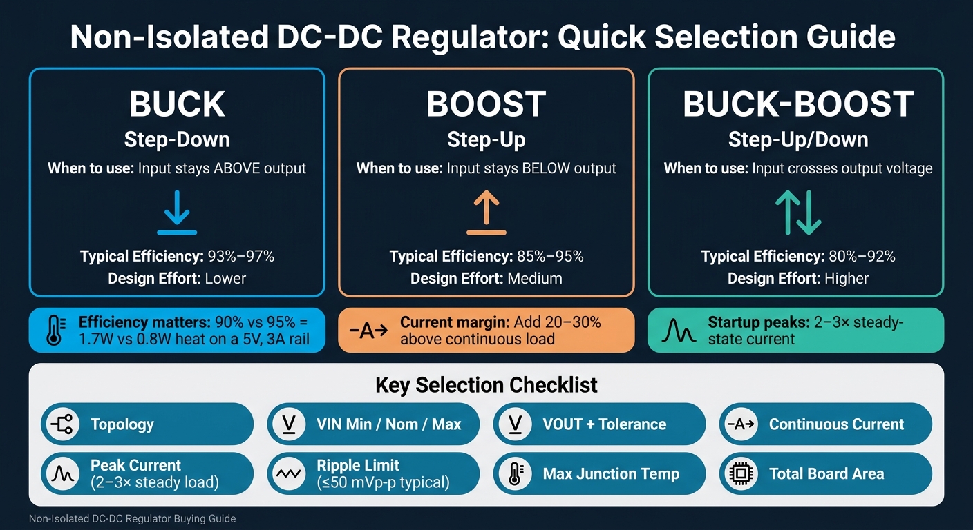
Non-Isolated DC-DC Regulator Types: Buck vs Boost vs Buck-Boost Compared
What Are Isolated Vs Non-Isolated DC-DC Converters? - Electrical Engineering Essentials
sbb-itb-501186b
Step 1: Define Voltage and Current Requirements
Once you’ve picked the topology, lock down the voltage and current limits before you start comparing datasheets. This step turns a broad design choice into a practical parts filter.
Set the Full Input Voltage Range and Output Target
Don’t size a regulator from the nominal voltage alone. For each input rail, write down all three values: V<sub>IN</sub>_MIN, V<sub>IN</sub>_NOM, and V<sub>IN</sub>_MAX. A “24 V” industrial control bus often runs from 18 V to 36 V. A 12 V automotive system can sag to about 9 V during cold-crank and rise to about 14.4 V when the alternator is charging. Your regulator has to handle that whole range all the time, not just the number printed on the label.
On the output side, common rails include 12 V, 5 V, 3.3 V, and 1.8 V or lower. Set a voltage tolerance for each one. ±5% works for many general-purpose digital loads. Mixed-signal and RF designs often need ±3% or tighter. That tolerance budget should also account for line regulation, load regulation, ripple, and transient droop.
Size the Current Rating With Adequate Margin
Keep steady-state current separate from startup peaks. Startup current can hit 2–3x the steady-state level.
After you total the continuous load, add 20–30% margin before choosing a regulator. So if your system needs 2.0 A continuously, look for a part rated for at least 2.4–2.6 A. It’s a simple move, but it can save you from running a part too close to the edge.
Use the basic power equation as a quick gut check:
P<sub>OUT</sub> = V<sub>OUT</sub> × I<sub>OUT</sub>
For example, a 5.0 V rail at 2.0 A needs 10.0 W. If startup current jumps to 3.0 A, that rail hits 15 W during the peak. Those numbers make it much easier to compare parts against their stated power limits.
Build a Requirements Summary Before You Shop
Write your spec first. Then shop. That gives design, purchasing, and manufacturing one shared reference, which helps avoid mix-ups later.
| Field | Example Entry |
|---|---|
| V<sub>IN</sub> range | 18 V min / 24 V nom / 36 V max |
| V<sub>OUT</sub> target | 5 V ±5% |
| Continuous I<sub>OUT</sub> | 2.0 A |
| Peak I<sub>OUT</sub> | 4.0 A (200 ms max) |
| Continuous P<sub>OUT</sub> | 10.0 W |
| Max ripple | ≤50 mVpp |
| Ambient temperature | 32–122 °F (0–50 °C), natural convection |
| Max board area | ≤0.75 in² for power stage and passives |
| Package constraint | SMD only (QFN, DFN, SOIC preferred) |
This summary gives you a clean way to screen parts in Step 2, especially for efficiency, ripple, and thermal limits.
Step 2: Compare Efficiency, Ripple, and Thermal Limits
Once you’ve summarized your requirements, you can start screening parts against three specs that shape day-to-day performance: efficiency, output ripple, and thermal headroom. These don’t live in separate boxes. They affect each other, so it makes sense to judge them as a set.
How to Read Efficiency Numbers Correctly
Check the efficiency curve at your actual V<sub>IN</sub>, V<sub>OUT</sub>, and I<sub>OUT</sub>. That matters because the efficiency number on the front page of a datasheet is usually a best-case figure. In practice, efficiency tends to drop at both light load and heavy load. So a regulator that looks great at full load can still burn more power than expected when the system spends time lightly loaded.
That lost power turns into heat. Using P_loss = P_out × (1/η − 1), a 5 V, 3 A rail gives you 15 W of output power. At 90% efficiency, the regulator dissipates about 1.7 W. At 95%, that falls to about 0.8 W.
That’s a big gap for what looks like a small change in efficiency. Half a watt here, another watt there, and suddenly your board runs hotter than planned.
Check Ripple and Noise Against Load Requirements
Output ripple is usually listed in millivolts peak-to-peak, or mVp-p. But that number only means something under the test setup used in the datasheet: a certain output capacitor mix, load range, and measurement bandwidth. If those conditions change, the ripple number can change too. So compare ripple figures only when the bandwidth, output capacitor, and load conditions match.
The ripple target depends on what you’re powering. General-purpose digital control logic can often live with around 50 mVp-p. But 16-bit ADCs, precision sensors, and RF transceivers may need ripple well below that if you want to avoid bad readings or link problems.
A practical move is to start with added ceramic capacitance. That’s usually the first lever to pull. Save LC or π filters for cases where you need tighter ripple limits, since those filters eat up board area and add BOM cost.
Verify Thermal Headroom at Real Ambient Temperatures
Thermal headroom is simply the gap between the maximum junction temperature and the worst-case operating temperature. A basic estimate looks like this:
T_J = T_ambient + P_loss × θ_JA
Here’s why that matters. A regulator with θ_JA = 40 °C/W dissipating 3 W inside a 122 °F (50 °C) enclosure will reach about 170 °C. That’s far past the limit. Room temperature is not the number to use here. Use the maximum enclosure temperature instead. If the math gets ugly, you may need more copper area or airflow to pull the temperature down.
The table below shows a sample trade-off for a 12 V to 5 V, 3 A rail on a U.S. embedded control board. In cases like this, ripple limits, heat, and board area usually decide which parts stay in the running.
| Spec | High-Efficiency IC | Lower-Cost Regulator + LC Filter |
|---|---|---|
| Efficiency (typical load) | 94–96% | 88–91% |
| Ripple (mVp-p) | 20–30 | 10–15 (with added filter) |
| Thermal headroom | Good at 85–104 °F (29–40 °C) with modest copper | Limited at higher ambient; needs extra copper |
| Board area (approx.) | ~0.6–0.8 in² | ~1.0–1.3 in² |
| Relative cost/complexity | Higher part cost, simpler design | Lower IC cost, higher BOM and layout effort |
Use these trade-offs to shrink the shortlist before you move on to package style and board space.
With electrical performance narrowed down, compare package style and board-space fit next.
Step 3: Choose Package Style and Board Space
Once you've narrowed down electrical performance, package choice becomes the next gate. And it matters more than it first appears.
Package choice affects assembly, heat flow, and total PCB area. For buyers, it also affects fit, assembly cost, serviceability, and sourcing risk.
IC Regulators vs. Power Modules
A regulator IC gives you control over the external power stage. You pick the inductor, capacitors, and layout based on what the design needs. A power module wraps the controller, FETs, and often the inductor into one package, with much of the power-path and thermal work already handled by the vendor.
That leads to a simple trade-off:
- Modules cut down on external parts and layout effort
- Discrete regulator ICs give you more freedom and usually lower component cost
Here’s a side-by-side view:
| Option | External Parts | Layout Complexity | Thermal Behavior | Board-Space Impact | Best-Fit Use Case |
|---|---|---|---|---|---|
| Regulator IC (e.g., QFN buck) | Inductor, capacitors, sometimes FETs and compensation parts | High - needs careful high-current loop and grounding design | Excellent with proper copper and vias; sensitive to layout quality | Smaller package, but total area grows with external parts and routing | High-volume designs, strong power-layout expertise, tight cost targets |
| Integrated power module | Few capacitors and configuration resistors | Low - vendor-optimized internally | Consistent; follow vendor copper recommendations | Larger local height and area per device, but fewer external parts can reduce total solution area | Fast time-to-market, limited layout resources, industrial designs |
Match Package Type to Assembly and Heat Dissipation
SOIC and TSSOP packages use gull-wing leads, so they’re easy to inspect and rework. That makes them a good fit for low-volume builds or field service. The downside is pretty plain: they have higher thermal resistance and take up more space.
QFN packages flip that trade-off. They’re harder to inspect, but they handle heat better. The exposed pad on the bottom ties straight into copper planes and thermal vias, which can bring junction-to-board thermal resistance down to 3–5 °C/W on a 4-layer board. That said, assembly needs tight reflow control, and high-reliability builds often call for X-ray inspection. Field rework is also tougher.
Module-style packages land somewhere in the middle. They assemble much like a large IC, but solder-paste volume and stencil design need close attention so you don’t end up with voiding under the thermal pad.
Estimate Total Board Area, Not Just Package Footprint
This is where teams sometimes get tripped up: package footprint is not the full story.
The real board area includes the inductor, input and output capacitors, keep-out zones around noisy switch nodes, and thermal copper pours. In many cases, that spreads across more than one layer. For higher-power converters, a common rule of thumb is to reserve about 1 in² of copper per PCB layer around the converter for heat spreading.
So even if one package looks tiny on paper, the full solution may not be.
| Package Style | Typical Total PCB Area | Thermal Performance | Assembly Difficulty | Best-Fit Use Case |
|---|---|---|---|---|
| Buck IC in SOIC/TSSOP | Larger total area once external parts are included | Moderate; relies more on leadframe conduction and surrounding copper | Easy - visual inspection and hand rework are straightforward | Moderate current, high serviceability needs |
| Buck IC in QFN | Smaller package, but external parts still drive the total area | High - low θJB when the exposed pad is tied to proper vias and copper | Moderate - requires reflow control and X-ray inspection | High-current, space-constrained designs |
| Integrated power module | Often smaller total solution area than a discrete design once routing and external parts are included | Consistent - vendor-characterized thermal path | Low-to-moderate - larger pads need stencil attention | Fast time-to-market, industrial or instrumentation designs |
A preliminary placement drawing is the best sanity check before approval. It helps confirm whether the part actually fits once routing, copper, and surrounding parts are taken into account. With package fit confirmed, build the procurement shortlist.
Step 4: Build a Procurement Checklist and Shortlist Parts
Once you've locked in voltage, current, efficiency, ripple, thermal limits, and package fit, turn that into a procurement checklist.
Use a Side-by-Side Regulator Evaluation Sheet
Start with a simple evaluation sheet for the parts on your shortlist.
First, filter by the basics: topology, input voltage range, output voltage, and current rating. If a part misses on any of those, stop there. There’s no point comparing the finer details.
After that, look at the things that usually decide the winner: efficiency at your expected load point, ripple and noise, thermal limits, package style, external component count, and total board area. Use the same fields for every part so you're making a clean, apples-to-apples comparison.
| Requirement | Option A | Option B | Notes |
|---|---|---|---|
| Topology | Buck | Buck | Both match |
| VIN range covers 9 V to 36 V | Yes | Yes, but with less margin | Option B has reduced high-line margin |
| VOUT = 5.0 V | Yes | Yes | - |
| IOUT ≥ 3 A continuous | 3 A rated | 4 A rated | Option B has more headroom |
| Efficiency at expected load point | Higher | Lower | Confirm test conditions |
| Ripple/noise within the allowable limit | Meets | Exceeds limit | Check measurement setup |
| Max junction temp ≤ 110 °C | Meets | Meets with airflow | Option B has less thermal margin |
| Package style | Suitable | Suitable with caveats | Confirm thermal and mounting requirements |
| External component count | Higher | Lower | Option B simpler to assemble |
| Total board area under 1.5 in² | Fits | Borderline | Option B is close to the limit |
Use the Notes column to flag trade-offs, call out red flags, and record why each part passed or failed. That small bit of context saves time later, especially when the shortlist gets reviewed by someone else.
Review Manufacturer Documents Before Approval
After the sheet cuts the list down, check each part against the manufacturer documents.
Read the full datasheet, reference layout, derating limits, and application notes before approval. The reference layout matters more than many teams expect. It can show PCB routing limits and placement rules that don’t stand out in the spec table. General electronics derating guidance commonly recommends operating semiconductors at ≤75% of rated voltage and ≤50% of rated power, with junction temperatures kept at or below 110 °C.
Also, make sure the test conditions line up with how you’ll actually run the part. A headline efficiency number at 12 V input, 5 V output, and 50% load might look fine on paper, but it may say very little about full-load performance or behavior at high ambient temperature.
One more thing: confirm that you're using the latest datasheet. Spec changes, including updated derating curves or revised maximum ratings, can affect compliance even when the part number looks unchanged.
Source Related Equipment Through Electrical Trader
If this purchase sits inside a larger build, it can help to source related items from one place. For broader procurement, Electrical Trader can also be used to source related electrical components and power equipment alongside the regulator shortlist.
Conclusion: Select by Requirements, Trade-Offs, and Fit
After Steps 1–4, the call gets pretty simple: choose the part that meets the topology, voltage/current, efficiency, ripple, thermal, and package limits at the same time.
First, make sure non-isolated is the right pick for that rail. Then rule out any part that fails the full input range or doesn’t leave enough current margin.
Think of efficiency, ripple, and thermal rise as one connected trade-off. Better efficiency cuts heat, sure, but a part only belongs on the shortlist if it also stays inside your noise and temperature limits. If the electrical side checks out, look at the physical fit next.
Check the total solution area, not just the IC footprint. In many designs, the inductor, capacitors, and copper area end up deciding the final fit and even assembly cost.
Write down why the selected part won, which trade-offs came with that choice, and what it replaced.
FAQs
How do I choose between buck, boost, and buck-boost?
Choose the converter type by comparing your input voltage to the output voltage you need.
- Buck: Use this when the input voltage is always higher than the output.
- Boost: Use this when the input voltage is always lower than the output.
- Buck-boost: Use this when the input voltage can move above and below the target output. A common case is a battery that starts full and then drops as it drains.
How much current margin should I add when sizing a regulator?
It depends on the load.
For general battery-powered devices, add 20%.
For industrial loads, motors, or welders, go with 30% to 50% above full load to handle startup inrush. That extra headroom matters because some equipment pulls more power the moment it kicks on.
If you expect future expansion, add another 10% to 25%. And for continuous duty, plan for an extra 20% above the nominal load to support long-term durability and help prevent overheating.
Why does total board area matter more than IC footprint?
Total board area matters more because a regulator needs more than just the IC. It also needs support parts like input and output capacitors, noise-reduction networks, and thermal features such as copper pours or heat sinks.
Those parts matter for stable performance, heat dissipation, and ripple control. So if you only look at the IC footprint, you won't get a clear picture of the actual PCB space the design needs.





