Top 5 Load Tap Changer Testing Methods
Load tap changers (LTCs) are critical for maintaining stable transformer output, but they’re also a leading cause of transformer failures. Regular testing can help identify issues early, avoiding costly outages. Here are five key methods to evaluate LTCs effectively:
- Static Winding Resistance Measurements (WRM): Detects contact wear and winding damage by measuring resistance at stationary tap positions.
- Dynamic Resistance Measurements (DRM): Analyzes switching performance during transitions to identify mechanical issues like contact bounce or misalignment.
- Dissolved Gas Analysis (DGA): Examines insulating oil for fault-indicating gases, signaling issues like arcing or overheating.
- Continuity and Discontinuity Detection Tests: Identifies "break-before-make" faults that can cause arcing and gas formation.
- Excitation Current Tests: Assesses the magnetic circuit and detects issues like shorted turns or core defects.
Each method targets specific failure modes, and combining them provides a thorough LTC health assessment. For instance, DGA can flag thermal stress, while DRM pinpoints the faulty component. Together, these tests help prevent transformer downtime and extend equipment life.
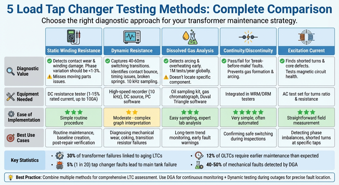
Comparison of 5 Load Tap Changer Testing Methods: Diagnostic Value, Implementation, and Use Cases
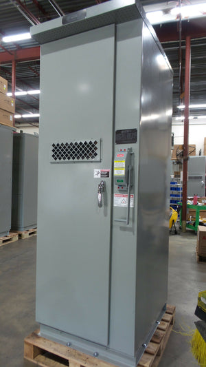
Testing and Commissioning an On-Load Tap Changer (OLTC) of a 50 MVA Transformer
sbb-itb-501186b
1. Static Winding Resistance Measurements
Static Winding Resistance Measurements (WRM) are used to assess stationary contacts and the condition of tap windings while the Load Tap Changer (LTC) remains at a specific tap position. This test works by passing a DC current through the winding and measuring the resistance at each tap. It’s particularly effective at identifying issues like contact wear, looseness, or misalignment - problems that can lead to overheating and the formation of coke, a solid residue created from oil breakdown.
This method is known for its accuracy. As DV Power explains:
"This type of test is very useful for detecting winding damages as well as the state of the static contacts in each tap position. With this method, it is possible to precisely locate any high-resistance contacts."
However, it has a limitation - it doesn’t capture problems related to moving parts or tap-transition failures, which are critical for understanding the full operational behavior of the LTC.
Diagnostic Value
Static WRM is particularly effective for identifying winding-specific issues, such as open or short-circuited turns within the tap windings. To interpret results, compare resistance values across phases and tap positions. Ideally, resistance values for each phase at a given tap should differ by no more than 1%, and phase-to-phase variations should stay within 3%. Deviations beyond these thresholds often indicate contact degradation or winding damage.
For example, during a field test in November 2023 on a 50 MVA transformer with an MR type M OLTC, resistance measurements across 25 taps showed phase deviations between 0.2% and 0.39%, well within IEEE C57.152 standards. However, subsequent dynamic testing revealed unstable contacts that static WRM alone could not detect. This highlights the importance of combining static and dynamic tests to catch early-stage degradation.
Equipment Requirements
Conducting static WRM requires specialized meters capable of delivering high DC test currents, typically ranging from 1% to 15% of the transformer's rated current. Advanced portable instruments can supply up to 100 A DC with 0.1% accuracy. Three-phase meters offer a significant advantage by enabling six-winding resistance measurements in a single setup, cutting down testing time compared to single-phase meters that require multiple reconnections.
Temperature sensors are also essential, as resistance values vary with temperature. These sensors record the winding material's temperature, allowing results to be adjusted to a standard reference temperature (commonly 75°F or 85°F) for accurate comparisons. Additionally, data analysis software helps create resistance graphs and track trends over time, providing a solid baseline for future evaluations.
Ease of Implementation
Static WRM is relatively simple to perform, but accuracy depends on proper execution. The DC test current must stabilize fully before recording resistance values. As Tony Wills, Team Leader Applications Engineer at Megger, advises:
"The resistance value should be observed closely to make sure it has stabilised before the value is recorded and stored."
For comprehensive results, measurements should be taken sequentially across all tap positions. Opposite windings (e.g., testing the high-voltage side while the low-voltage side remains disconnected) must stay open-circuited during testing to ensure accuracy. While static WRM provides a reliable baseline, pairing it with dynamic tests is essential for a complete LTC evaluation.
Best Use Cases
Static WRM is particularly useful for:
- Routine condition checks to establish a baseline during new transformer acceptance.
- Post-maintenance verification, ensuring that repairs like tightening bolts or cleaning contacts have restored normal resistance levels.
- Baseline creation to monitor trends throughout the transformer's operational life.
Because static WRM only evaluates stationary conditions, it works best as part of a broader testing strategy. Incorporating dynamic tests offers a more complete view of the LTC's overall health.
2. Dynamic Resistance Measurements
Dynamic Resistance Measurements (DRM) focus on capturing the LTC's performance during the critical 40 to 60 milliseconds when contacts move and transition resistors engage. This method provides a detailed view of tap changer transitions, helping identify issues like contact bouncing, broken springs, or misalignment.
DRM involves injecting a DC current through the winding while the tap changer is in operation. High-speed data acquisition - at 10 kHz - records every detail of the switching process. Unlike static testing, DRM evaluates components such as diverter resistors and bridging reactors that are active only during transitions.
Diagnostic Value
DRM is highly effective at uncovering faults that other methods might miss. For instance, in November 2023, a 40 MVA, 132 kV/11.5 kV transformer showed high dissolved gas levels, including methane at 261.58 ppm and ethane at 525.96 ppm. Despite normal results from standard electrical tests, DRM pinpointed unstable current in Phase C, directing attention to its selector contacts and avoiding unnecessary disassembly of all three phases.
By analyzing transition ripple, duration, and waveform shape, DRM identifies problems like "break-before-make" failures or mechanical wear. A 100% ripple, for example, signals a dangerous "break-before-make" condition, while extended transition times may indicate worn components or broken springs. Dr. Raka Levi, an expert at DV-Power, highlights the method's growing importance:
"The DRM methodology is only 10- to 15 years old, but it has shown a great potential in detecting problems otherwise invisible to repair technicians."
DRM also excels at catching early-stage issues. In another November 2023 case, a 50 MVA transformer showed minimal deviations (0.2% to 0.39%) in static winding resistance measurements. However, DRM detected unstable current during transitions, uncovering insulating layers on the contacts that static tests failed to detect.
To achieve these detailed insights, specialized equipment is essential.
Equipment Requirements
Performing DRM requires precise tools to capture rapid transitions. Specialized tap changer analyzers are used to inject a stable DC current - ranging from 0.1 A up to 15% of the transformer's rated winding current - and must include high-frequency data acquisition systems (10 kHz or greater) capable of recording transitions lasting under 100 milliseconds. Advanced systems can simultaneously measure test current and the voltages on both high-voltage (HV) and low-voltage (LV) windings. By modeling the transformer, these systems eliminate inductance effects for more accurate resistance readings, even allowing direct calculation of transition resistor values. PC-based software then processes the data, generating DRM graphs and calculating ripple and timing for comparison with historical benchmarks.
For improved sensitivity, short-circuiting the transformer's secondary side is recommended. This reduces the time constant (L/R ratio), effectively doubling current ripple amplitude and making defects easier to spot.
Ease of Implementation
DRM is non-intrusive and uses the same lead connections as static tests, with measurements taken during tap changer rest periods . A practical advantage is that unstable current detected before a transition can sometimes be resolved on-site. By operating the OLTC multiple times with a high test current, arcing can burn off insulating layers - like silver sulfide deposits - potentially restoring functionality without needing disassembly.
Best Use Cases
Integrating DRM with other testing methods provides a complete picture of LTC health. DRM is particularly useful in several scenarios:
- Complementing dissolved gas analysis (DGA): While DGA indicates abnormal gas generation, DRM pinpoints the specific tap changer component responsible.
- Routine maintenance: Establishing baselines for new or healthy tap changers helps identify early maintenance needs. Studies show that about 12% of OLTCs require earlier maintenance than expected.
- Post-repair verification: DRM confirms whether repairs - like tightening bolts or replacing springs - have restored proper timing and contact stability.
- Three-phase synchronization testing: Ensures multiple tap changers on the same drive operate in sync.
For consistent results, always perform DRM tests in the same direction (e.g., from position 16L to 16R). Overlaying DRM graphs with motor current recordings can help differentiate electrical contact issues from mechanical friction.
3. Dissolved Gas Analysis (DGA) of Insulating Liquids
Dissolved Gas Analysis (DGA) is a diagnostic method used to examine insulating oil in tap changers, identifying fault-indicating gases. When arcing or overheating occurs, the insulating oil degrades, releasing specific gases. For example, acetylene suggests severe arcing, ethylene points to high-temperature thermal issues (above 700°F), and methane indicates lower-temperature faults (below 570°F).
Globally, around 1,000,000 DGA tests are conducted annually, making it a widely used tool for diagnosing load tap changers. The Duval Triangle, a method introduced in the 1970s, uses the ratios of acetylene (C₂H₂), ethylene (C₂H₄), and methane (CH₄) to classify faults into distinct zones, such as partial discharge, thermal faults, or high-energy arcing. This chemical analysis complements electrical testing by identifying thermal or electrical stresses before they cause mechanical damage.
Diagnostic Value
DGA is particularly effective at detecting mechanical faults that would otherwise require disassembly to uncover. These mechanical issues are responsible for 40% to 50% of problems in high-voltage circuit breakers and tap changers. As I.G.P. Yudiastawan from Power Prognosis explains:
"DGA is one of the most reliable ways to truly 'listen' to what a transformer is telling us."
This makes DGA a key component of a comprehensive testing strategy. While it identifies whether burning, overheating, or arcing is occurring, pairing DGA with tools like dynamic resistance measurements helps pinpoint the exact faulty component.
Equipment Requirements
Accurate DGA results depend on specialized equipment. Gas chromatographs are essential for extracting, separating, and measuring individual gases from oil samples. Modern online monitoring systems have sensors that continuously track gas levels in real time, offering early warnings of potential issues. Diagnostic software, such as DGAView, simplifies analysis by plotting gas data into the Duval Triangle, minimizing interpretation errors.
Proper sampling is critical - oil must be taken directly from the tap changer compartment to avoid contamination. Additionally, gas chromatographs require routine calibration to ensure precise parts-per-million (ppm) measurements.
Ease of Implementation
DGA is widely accessible, with both laboratory services and online monitoring systems available globally. Its non-intrusive nature allows it to be performed during normal operation, making it ideal for routine maintenance. Standards like IEEE C57.139 provide guidelines for interpreting gas concentrations in load tap changers. DGA protocols can also be adjusted based on specific LTC designs.
Best Use Cases
DGA is most effective when used as part of a routine monitoring strategy. It helps establish baselines, validate results from other tests, and track trends over time. Key applications include:
- Establishing baselines: Initial DGA readings on new or newly installed transformers provide reference points for future comparisons and help identify early issues, such as arcing during startup.
- Complementing other diagnostics: When DGA detects abnormal gas levels, follow-up tests like dynamic resistance measurements can locate the fault. While DGA identifies chemical changes, resistance tests reveal physical damage like contact wear or winding issues.
- Monitoring between inspections: Online DGA sensors offer continuous monitoring, enabling early detection of problems before they escalate.
To maximize its effectiveness, DGA should be paired with proper sampling techniques and cross-validated with other diagnostic tests, as it cannot always pinpoint the exact fault location on its own.
4. Continuity and Discontinuity Detection Tests
Continuity and discontinuity detection tests are designed to spot "break-before-make" conditions, where the circuit briefly disconnects during a tap change. These interruptions can lead to gas formation, heavy arcing, and even transformer tripping or failure. By identifying the exact fault location, these tests work hand-in-hand with other diagnostic methods to provide a thorough LTC evaluation. As Dr. Raka Levi from DV-Power points out:
"Opening the circuit is one of the biggest OLTC problems. It creates gases and can cause transformer tripping or even a failure."
These tests rely on high-frequency recording to capture transitions that typically last only 40 to 60 milliseconds. Unlike dissolved gas analysis, which only signals that an issue exists, continuity tests pinpoint specific faults, such as broken springs, faulty leads, or loose connections. When paired with static and dynamic testing, this approach offers a more complete picture of the LTC's condition.
Diagnostic Value
Once interruptions are detected, it’s crucial to evaluate their impact. Continuity tests examine the health of all components conducting current during operation, such as diverter switches and transition resistors. They uncover faults that static winding resistance tests might miss, as those only measure conditions at rest. With 1 in 20 tap changer faults leading to main tank failures, early detection through these tests can help avoid costly outages.
Equipment Requirements
To perform these tests, you'll need a DC current source (ranging from 0.1 A to about 15% of the transformer's rated winding current), a high-frequency data recorder with a sampling rate of at least 10 kHz, and analysis software to interpret current drops . Modern digital winding resistance testers often include continuity testing capabilities, using the same leads as standard resistance measurements.
Ease of Implementation
These tests are non-destructive and can be performed off-line without opening the OLTC compartment or draining oil. They can even run alongside standard resistance measurements, minimizing downtime . The analysis is straightforward - any sudden 100% ripple or current drop is easy to spot on a graph.
Best Use Cases
Continuity tests are ideal during commissioning to establish a baseline for future comparisons. They’re especially useful for verifying repairs - always retest after corrective actions like tightening bolts to confirm the issue has been resolved. For better sensitivity, try short-circuiting the transformer's secondary side; this reduces inductance and makes current ripples more noticeable. Consistency is key - standardizing the test direction ensures reliable current trace comparisons over time.
5. Excitation Current Tests
When evaluating LTC components, excitation current tests offer a closer look at the magnetic circuit's health. These tests measure the current needed to magnetize a transformer’s core, helping to identify problems that might slip past other diagnostic methods. Testing across multiple tap positions improves accuracy. As M.F. Lachman from Doble Engineering Co. notes:
"The single-phase exciting-current test can be used to detect undesirable conditions in single- and three-phase transformers. Certain problems, however, can be detected on the basis of current change when the measurements are performed on different load tap changer positions."
By the mid-1990s, over 80 utilities were already using advanced data acquisition systems with expert software to automatically analyze excitation current patterns - 12 distinct behaviors have been identified across various LTC designs.
Diagnostic Value
Excitation current tests are particularly useful for assessing the condition of moving contacts, stationary contacts, and tap winding sections. While winding resistance tests are better at spotting high-resistance connections, excitation current tests excel at detecting magnetic circuit issues and shorted turns . In a healthy transformer, current patterns remain consistent across all three phases . Variations in these patterns can indicate problems such as shorted turns, core defects, or misalignments in the LTC . This makes excitation current testing a strong complement to other diagnostic methods, as it focuses on magnetic and core-related issues that might otherwise go unnoticed.
Equipment Requirements
To perform these tests, use diagnostic tools that can also measure turns ratio and winding resistance . The procedure involves applying a single-phase AC voltage to one winding while leaving the others open-circuited. You’ll need to step through each tap position, allowing time for stabilization before recording data with an integrated acquisition system . Combining excitation current tests with static and dynamic measurements ensures a thorough evaluation of the LTC.
Best Use Cases
Excitation current tests are valuable during both commissioning and maintenance. As part of commissioning, they establish a baseline "fingerprint" for future reference. They’re especially helpful when dissolved gas analysis (DGA) flags a potential issue, as they can pinpoint whether the problem is tied to specific tap positions or winding sections . Testing at multiple tap positions is crucial since certain faults may only appear at specific points along the LTC’s range. Additionally, understanding the design of your LTC is key, as different designs can affect current magnitude in unique ways.
Comparison Table
Choosing the right testing method depends on what you're trying to diagnose and the tools you have on hand. Here's a breakdown of how different methods perform across several key factors:
| Testing Method | Diagnostic Value | Ease of Implementation | Equipment Requirements | Best Use Case |
|---|---|---|---|---|
| Static Winding Resistance | Great for spotting high-resistance contacts and winding damage; doesn’t provide insight into moving parts or switching faults. | Simple – a routine procedure that requires moderate expertise. | DC winding resistance tester. | Routine maintenance; identifying high-resistance connections and ensuring phase readings stay within 1–3%. |
| Dynamic Resistance | Offers a detailed look at switching processes, timing, and transition resistors; detects contact bounce and "make-before-break" issues with high-frequency sampling (0.1 ms resolution). | Moderate – involves interpreting complex graphs and requires specialized skills. | High-speed DC recorder (up to 10 kHz sampling) and PC software for analysis. | Diagnosing mechanical wear, coking, and transition resistor failures; ensuring switching times stay within 40–60 ms. |
| Dissolved Gas Analysis | Excellent for spotting early signs of thermal and electrical faults like arcing and overheating; doesn’t isolate the specific failing component within the OLTC. | Easy for collecting field samples, though lab interpretation demands expertise. | Oil sampling kits and lab gas chromatographs. | Monitoring long-term trends and providing early fault warnings. |
| Continuity/Discontinuity | A dependable "pass/fail" test to ensure no interruptions occur during tap changes; critical for avoiding major switching failures. | Very simple – often built into modern WRM or DRM equipment. | Typically integrated into winding or dynamic resistance testers. | Confirming safe "make-before-break" switching during routine inspections. |
| Excitation Current | Useful for detecting short-circuited turns and magnetic circuit problems, especially in reactance-type OLTCs. | Straightforward – standard field measurement at stationary tap positions. | AC test set for measuring turns ratio and winding resistance. | Checking for shorted turns at specific taps and diagnosing phase imbalances. |
Each method brings something different to the table, making a combined approach the best way to thoroughly evaluate LTCs.
Static tests, for instance, are great for ensuring phase variation stays minimal, while dynamic tests shine in spotting mechanical issues - like switching times that exceed 60 ms, which often signal major problems. Dissolved gas analysis (DGA), on the other hand, detects fault byproducts but doesn’t pinpoint their exact location.
The smartest strategy? Use DGA for ongoing monitoring to catch early signs of trouble, then follow up with dynamic resistance tests during outages to locate faults without taking the unit apart. This is especially critical given that aging OLTCs cause about 30% of substation transformer outages, and 1 in 20 tap changer faults can lead to main tank failure.
Conclusion
When it comes to assessing the health of load tap changers (LTCs), no single test can do it all. Each diagnostic method brings something different to the table. Static winding resistance tests are great for spotting high-resistance contacts, but they can miss issues during switching. Dynamic resistance tests, on the other hand, uncover timing problems and worn transition resistors. Meanwhile, dissolved gas analysis (DGA) is invaluable for detecting early signs of thermal stress, though it can't pinpoint the exact faulty component. Together, these tools form a powerful combination, compensating for each other's limitations.
The statistics highlight why this is so important. About 30% of substation transformer failures are linked to aging LTCs, and 5% of tap changer faults lead to main tank failures. These failures can result in expensive outages - issues that comprehensive testing can often prevent.
The key to effective transformer maintenance lies in layering these diagnostic methods. Start with DGA for continuous monitoring to catch early warning signs. During outages, dynamic resistance testing can pinpoint faults without the need for disassembly. Add continuity tests to confirm proper make-before-break operation, and include excitation current tests to uncover potential core and winding problems. This multi-method approach not only identifies defective components but also helps you address them before they escalate into major failures. The result? Smarter maintenance schedules and less downtime.
To make this layered approach work, having the right tools is non-negotiable. Platforms like Electrical Trader offer specialized equipment, from winding resistance meters to high-frequency recorders, making comprehensive LTC testing easier and more efficient. With the right gear in hand, keeping your transformers in top shape becomes much more manageable.
FAQs
How often should an LTC be tested?
Regular testing of an LTC is essential, with maintenance schedules usually based on the number of operations or the amount of operating time. Always consult the manufacturer's operating and inspection manuals for detailed guidance tailored to the specific equipment.
Which test should I run first when DGA looks abnormal?
If the results from the dissolved gas analysis (DGA) seem unusual, the first step is to revisit the analysis to pinpoint any potential issues within the transformer or load tap changer. To further localize the fault, the DVtest (Dynamic Resistance Measurement) method can be a helpful addition. This non-intrusive diagnostic tool is effective for confirming and accurately identifying problems.
What does a 100% ripple in DRM mean?
A 100% ripple in Dynamic Resistance Measurement (DRM) indicates a complete fluctuation in electrical resistance while an On-Load Tap Changer (OLTC) is in operation. This could point to problems like contact wear, misalignment, or internal faults within the tap changer. Identifying these variations during testing can help detect potential issues early on.