
How Intrinsically Safe Equipment Is Certified
If the label, certificate, and control drawing do not match, I would not install the device. That is the short answer.
I see this process as a 3-part check:
- Match the device to the hazardous area: Class/Division or Zone, gas group, and T-code
- Check the full IS loop: field device, barrier or isolator, and cable
- Verify the paperwork: NRTL listing, certificate number, and control drawing
Here’s the plain-English version:
- In the U.S., IS equipment for hazardous locations is usually approved by an OSHA-recognized NRTL such as UL, FM, CSA, or ETL
- For many U.S. IS applications, UL 913 is a main standard; Zone-based work often uses UL 60079-11
- The system has to stay below ignition energy in normal use, one fault, and two faults
- Entity parameter checks matter: Vmax ≥ Voc, Imax ≥ Isc, and total cable/device capacitance and inductance must stay within allowed limits
- ATEX-only marking is not enough for U.S. approval
- A small field change - like a different cable length or replacement part - can void the approved setup
A few numbers stand out:
- Production audits are often done every 6 to 12 months
- IS wiring should be separated from non-IS wiring by 2 in. (50 mm) or a grounded metal barrier
- A zener barrier ground should be below 1 ohm
How to get an IECEx Certificate for equipment intended for use in a hazardous location?
sbb-itb-501186b
Quick check before you buy or install
| Check | What I look for | Pass/Fail trigger |
|---|---|---|
| Area rating | Class/Division or Zone matches site | Any mismatch |
| Gas group | Label fits site gas group | Lower-rated group than site |
| T-code | Device surface temp stays below site ignition temp | T-code too hot for site |
| Entity values | Voltage, current, capacitance, inductance all match | Any value outside limits |
| Certificate | NRTL record matches model and suffix | Record missing or different |
| Control drawing | Drawing matches planned wiring and cable | Wiring differs from drawing |
So if I had to sum up the article in one line, it would be this: IS certification is not just about one approved device; it is about one approved system, installed exactly as documented.
Intrinsic Safety Certification Basics
Certification comes down to three checks: the governing standard, the area classification, and the circuit’s electrical limits. Those are the gates certifiers look at before they grant approval.
Key Standards: UL 913, ATEX, and IECEx
UL 913 is the main North American IS standard. For Zone-based systems, use UL 60079-11, which lines up with IEC 60079-11 and is used for ATEX and IECEx. ATEX and IECEx follow different marking rules and approval paths. If you’re buying imported equipment or working with a package specified for more than one market, check which approval scheme the site calls for.
Once the standard is set, the next step is to match the device to the area classification.
Hazardous Area Classification and Protection Levels
The area classification tells you what level of IS approval the device must have. Gas group and temperature class narrow the match even more.
Gas groups show how easily a gas can ignite. A device rated for Group A can be used in Groups B, C, and D. A Group D rating does not cover B or C. That rating decides whether a device can be certified for use in a given atmosphere.
The T-code sets the maximum surface temperature under fault conditions. That temperature must stay below the gas’s autoignition temperature.
| T-Code | Max Surface Temp | Typical Application |
|---|---|---|
| T1 | 450°C (842°F) | Hydrogen, high AIT gases |
| T3 | 200°C (392°F) | Gasoline vapors, some solvents |
| T4 | 135°C (275°F) | Acetaldehyde, diethyl ether |
| T6 | 85°C (185°F) | Rarely required in practice |
Entity Parameters and Associated Apparatus
IS certification applies to the entire system: the field device, the associated apparatus such as a barrier or isolator, and the cable. A label on one device isn’t enough if the system values don’t line up.
Zener barriers need a dedicated IS ground. Galvanic isolators do not.
Compatibility is checked through entity parameters. The math has to work: Vmax ≥ Voc, Imax ≥ Isc, and total capacitance and inductance must stay within Ca and La. Cable capacitance and inductance also count toward those totals.
The control drawing is the manufacturer-supplied document that spells out every allowed connection, cable type, and component in the system. It carries the certification from design into installation.
"Intrinsic safety is a system concept... The control drawing is the master plan for everything in an IS system." - Mark Lamendola, Electrical Consultant
Any change from the control drawing voids the approval .
That drawing then becomes the basis for testing and final certification.
Step-by-Step Process for Certifying Intrinsically Safe Equipment
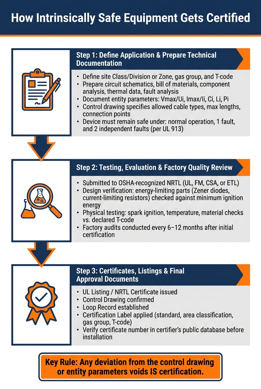
How Intrinsically Safe Equipment Gets Certified: 3-Step Process
Certification usually moves in a simple order: define where the equipment will be used, send the design in for review, and gather the approval paperwork.
Step 1: Define the Application and Prepare Technical Documentation
Once the control drawing and entity limits are set, the process starts with a complete application package. Before anything goes to the lab, you need to define the target site class, zone, gas group, and T-code.
The technical file usually includes circuit schematics, a bill of materials, component analysis, thermal management data, and a fault analysis. Under UL 913, the device must stay safe during normal operation, one fault, and two independent faults.
The control drawing is the binding document for the installation. It spells out the allowed cable types, maximum cable lengths, connection points, and components in the IS loop. The entity parameters - Vmax/Ui, Imax/Ii, Ci, Li, and Pi - also need to be defined and documented. If someone drifts from the control drawing or the entity parameters, the intrinsic safety of the circuit can be voided.
Step 2: Testing, Evaluation, and Factory Quality Review
After the documents are submitted, an OSHA-recognized NRTL handles the type evaluation. That review includes both design verification and physical testing.
On the design side, engineers check that energy-limiting parts, such as Zener diodes and current-limiting resistors, are sized so electrical energy stays below the minimum ignition energy of the target gas group.
Testing covers spark ignition, temperature, and material checks against the declared T-code. Factory audits are part of the process too. After the first certification, manufacturers go through periodic production audits, usually every 6 to 12 months, to make sure manufacturing controls still line up with the approved design.
If the design clears review, the lab issues the approval documents that installers need to match to the nameplate.
Step 3: Certificates, Listings, and Final Approval Documents
When testing is complete and the device passes, the certifier issues the formal approval records. Installers and buyers should have these documents on file before the equipment goes into service:
| Document | What It Confirms |
|---|---|
| UL Listing / NRTL Certificate | Equipment passed type testing under the applicable standard |
| Control Drawing | Specifies allowed cable types, cable lengths, connection points, and components in the IS loop |
| Loop Record | Records the complete loop as an interconnected IS system |
| Certification Label | Shows the standard, area classification, gas group, and temperature code |
For U.S. sites, check the NRTL mark and make sure the control drawing matches before purchase. Then use those same documents to confirm the label before installation.
How to Read and Verify Intrinsically Safe Markings
Decode Labels, Ex Markings, and Temperature Classes
With the certificate and control drawing in hand, check that the nameplate matches the approved system.
Start by matching the protection level on the label to the site classification.
Then confirm that the label’s gas group and T-code fit the site classification. A higher group rating can cover lower-risk groups. A lower rating cannot cover a higher-risk gas. The T-code also needs to keep the maximum surface temperature below the autoignition temperature of the site gas.
Next, verify Ui/Vmax, Ii/Imax, Pi/Pmax, Ci, and Li against the limits for the associated apparatus and the cable.
If any code doesn’t match the approved documents, stop there and verify it before wiring.
Verify Listings, Certificate Numbers, and Control Drawings
Once the label checks out, look at the certificate record behind it.
Don’t rely on the label by itself. Before installation, verify the certificate number in the certifier’s public database. Reject any model, suffix, or certificate number that doesn’t match the database record.
ATEX-only markings do not meet U.S. approval rules. ATEX marking by itself does not equal U.S. NRTL approval.
The last check is the installation limits shown on the control drawing. Then make sure the label’s referenced control drawing matches the installation plan.
Maintaining Compliance and Sourcing Certified Equipment
Manage Changes, Repairs, and Periodic Verification
After certification, the loop needs to stay exactly as approved. Once the equipment is in place, compliance depends on keeping that approved loop intact.
Even a small change can knock the loop outside the approved energy limits. A different transmitter, a longer cable run, or a replacement part that isn't identical can void certification. Before you swap any field device, check that Voc ≤ Vmax and Isc ≤ Imax. Then confirm that total circuit capacitance and inductance, including the cable, still fit within the barrier's Ca and La limits.
Don't field-repair IS protection parts. Send repairs to the manufacturer or an authorized facility. Periodic inspection matters too. Check the loop for barrier damage, ground degradation, and wiring separation faults in line with IEC 60079-17. Also, keep the control drawing at the barrier cabinet and in maintenance files.
A few installation details can't slip:
- Keep IS wiring separated from non-IS wiring by 2 in. (50 mm) or by a grounded metal barrier
- Mark IS wiring with blue insulation, jackets, or labels to avoid cross-connection
- Keep the zener barrier's dedicated ground below 1 ohm
Source Equipment with Clear Certification Records
For new purchases, check the approval record before the equipment arrives on site. For a U.S. installation, look for a current NRTL mark such as UL, FM, CSA, or ETL, a valid certificate number that can be checked in the certifier's public database, and a control drawing that matches the installation plan.
You also need to confirm that the T-rating stays below the site's autoignition temperature. And the Class, Division, and Gas Group on the label must match the hazardous location.
Conclusion: Key Steps to Certify and Verify IS Equipment
Ongoing verification is part of compliance. It isn't something to deal with later. Keep the loop unchanged, verify each replacement against the control drawing, and recheck entity parameters before putting the system back into service.
FAQs
What makes equipment intrinsically safe?
Equipment is intrinsically safe when its electrical and thermal energy stays below the point that could ignite a flammable atmosphere. In plain English: even during normal use or if something goes wrong, it can't produce a spark or surface temperature hot enough to ignite gases, vapors, or dust.
Engineers make that happen by limiting current, voltage, and stored energy. Then certification bodies check those protections through strict testing.
Can I use ATEX-only equipment in the U.S.?
No. In the United States, equipment with only ATEX certification cannot be used legally.
ATEX is an EU directive. In the U.S., hazardous-location equipment must be certified by an OSHA-recognized NRTL such as UL, FM Approvals, CSA, or Intertek, and it must meet NEC requirements.
What can void IS certification?
IS certification can be voided by unauthorized modifications, poor maintenance, or by brushing off damage like cracks, dents, or loose screws.
For system-approved setups, the same applies if you swap components, change cable lengths, replace a device with a different model without re-evaluation, or ignore the control drawing’s wiring methods or entity parameters.


