
FAQs on Intrinsic Safety Standards
Intrinsic safety (IS) ensures electrical equipment operates safely in hazardous environments by limiting energy to prevent sparks or heat that could ignite explosive atmospheres. Governed by standards like IEC 60079-11, ATEX 2014/34/EU, and UL 60079-11, IS systems are crucial for industries like oil, gas, and manufacturing. These systems include devices, barriers, and cables designed to work together as a complete, certified setup.
Key takeaways:
- IS Standards: IEC 60079-11 (global), ATEX (EU), UL 60079-11 (US), CSA C22.2 No. 60079-11 (Canada).
- Protection Levels: Ex ia (Zone 0), Ex ib (Zone 1), Ex ic (Zone 2).
- IS Systems: Include intrinsically safe devices, associated apparatus (e.g., barriers), and connecting cables.
- Barriers: Zener barriers (simple, cost-effective) vs. isolating barriers (no grounding, easier maintenance).
- Compliance: Entire systems must meet certification requirements, with regular inspections and documentation.
IS systems reduce risks in hazardous areas while allowing live maintenance. Proper installation, certification, and adherence to standards ensure safety and legal compliance.
Core Principles of Intrinsic Safety
Energy Limitation and Fault Tolerance
Intrinsic safety works by limiting voltage, current, and power to levels that prevent sparks or excessive heat - essentially removing the ignition source from the combustion triangle.
For most devices, energy is capped at 29 V, 300 mA, and 1.3 W, though these thresholds can vary depending on the ignition properties of specific gases. The system’s design must ensure safety even if components fail, making integrated circuit design critical. As Roger Highton, MTL Product Line Manager at Eaton, explains:
"The IS technique relies on the system being correctly designed and intrinsic safety becomes a system concept."
This underscores the importance of evaluating the entire circuit - field devices, barriers, and wiring - rather than isolating individual components.
Equipment Protection Levels
Intrinsic safety classifications are based on fault tolerance, which determines where the equipment can be safely used. The table below summarizes these classifications:
| Protection Level | Fault Tolerance | Suitable Zones | Safety Level |
|---|---|---|---|
| Ex ia | Tolerates two faults | Zone 0, 1, 2 | Very High |
| Ex ib | Tolerates one fault | Zone 1, 2 | High |
| Ex ic | Normal operation only | Zone 2 | Normal |
Ex ia offers the highest level of safety and is the only classification allowed in Zone 0 - areas where explosive atmospheres are constantly present. Ex ib applies to Zone 1, where hazardous conditions occur intermittently, while Ex ic is used in Zone 2, where such conditions are rare under normal operations. A key advantage of intrinsic safety is that energized equipment can be maintained without shutting down the plant.
IS Apparatus and Associated Devices
Intrinsic safety systems rely on a dual-apparatus approach. These systems consist of:
- Intrinsically safe apparatus: Devices like sensors or transmitters located in hazardous areas.
- Associated apparatus: Barriers or isolators installed in safe areas to enforce energy limits.
There are two main types of interfaces:
| Feature | Zener Barriers | Isolating Barriers |
|---|---|---|
| Grounding | Requires a dedicated, high-integrity safety earth | No safety earth needed; provides galvanic isolation |
| Complexity | Simple, loop-powered | More complex; uses active electronics |
| Maintenance | Needs regular earth testing | Easier inspections; allows higher voltage to field devices |
Zener barriers are cost-effective but depend on a reliable safety earth connection. Isolating barriers, on the other hand, use galvanic isolation, removing the need for grounding and reducing maintenance efforts. This makes them a popular choice in modern setups.
Additionally, low-energy devices like switches, thermocouples, and LEDs fall under the simple apparatus category. These operate below 1.5 V, 0.1 A, and 25 mW, so they don’t need formal intrinsic safety certification, although they must be documented as part of the system.
sbb-itb-501186b
Understanding Intrinsically Safe Systems per the NEC
International Standards: IEC and ATEX
ATEX vs IECEx vs NEC: Intrinsic Safety Standards Compared
IEC Standards for Intrinsic Safety
International standards play a key role in ensuring the consistent application of intrinsic safety principles. Among these, IEC 60079-11 stands out as the go-to standard for the construction and testing of intrinsically safe devices and associated apparatus in explosive atmospheres. The latest version, IEC 60079-11:2023, spans 209 pages and received its most recent corrections in May 2026. This standard is part of the larger IEC 60079 series, which also addresses hazardous area classifications (IEC 60079-10-1 and 10-2) and system-level verifications (IEC 60079-25).
The 2026–2027 update cycle brought stricter regulations around PCB spacing, copper thickness, separation distances, and battery testing, pushing manufacturers to redesign circuits to meet these new criteria. Jeff Lenk, Lead of Worldwide Transformation of Product Development at Nemko, emphasizes the importance of staying ahead of these changes:
"Standard evolution is essential for improving safety in hazardous environments, but it also introduces complexities for manufacturers. The organisations that succeed are those that act early."
For manufacturers, it's critical to align each product with the specific IEC edition cited in their documentation. This helps identify which updates necessitate redesigns or retesting.
ATEX Requirements in the European Union
In the European Union, ATEX serves as the mandatory legal framework for equipment used in explosive atmospheres. Governed by Directive 2014/34/EU, ATEX compliance is legally required for any equipment sold within the European Economic Area (EEA). Unlike IECEx, which operates as a voluntary international scheme, ATEX carries the weight of law across the EU.
ATEX categorizes equipment into Groups and Categories.
- Group I: Covers mining applications.
- Group II: Applies to surface industries.
Within Group II, Categories 1, 2, and 3 correspond to Zone 0, Zone 1, and Zone 2 for intrinsic safety. For example, Category 1 aligns with Ex ia, Category 2 with Ex ib, and Category 3 with Ex ic. This classification system ensures consistency with intrinsic safety standards.
Interestingly, ATEX allows manufacturers to use IEC standards as a "deemed to comply" route, offering some flexibility in how they demonstrate conformity.
IEC vs. ATEX: Side-by-Side Comparison
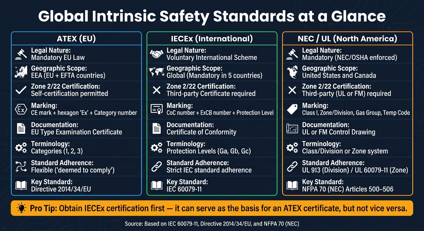
Despite sharing the same technical foundation since 2005, IEC and ATEX differ significantly in terms of legal requirements, certification processes, and marking conventions. Here’s a breakdown of the key distinctions:
| Attribute | ATEX | IECEx |
|---|---|---|
| Legal Nature | Mandatory EU Law | Voluntary International Scheme |
| Geographic Scope | EEA (EU + EFTA) | Global (Mandatory in 5 countries) |
| Zone 2/22 Certification | Self-certification permitted | Third-party Certificate required |
| Marking | CE mark with hexagon "Ex" and Category | CoC number, ExCB number, and Protection Level |
| Documentation | EU Type Examination Certificate | Certificate of Conformity |
| Terminology | Categories (1, 2, 3) | Protection Levels (Ga, Gb, Gc) |
| Standard Adherence | Flexible ("deemed to comply") | Strict adherence to IEC standards |
For manufacturers aiming to access both markets, a smart approach is to first secure an IECEx Test Report. This report can then serve as the foundation for obtaining an ATEX certificate. However, the reverse process is not possible. As Ex-Machinery B.V. explains:
"One IECEx certificate can be used as the basis for an ATEX certificate, but not the other way around."
North American Standards: NEC, NFPA, and UL
NEC and NFPA Requirements
The National Electrical Code (NEC), also known as NFPA 70, is a unified code published by the National Fire Protection Association. It provides the framework for hazardous location classification in North America. Articles 500–504 outline the Class/Division system, while Articles 505–506 introduce the Zone system, which was added in 1996 to better align with international IEC standards. Specifically, Article 504 focuses on installation rules for intrinsically safe (IS) systems, detailing requirements like wiring separation, grounding, and circuit labeling.
To determine the proper zone or division for a specific area, engineers refer to two related NFPA documents: NFPA 497 (for flammable gases and vapors) and NFPA 499 (for combustible dusts). These documents provide the engineering guidelines needed for accurate area classification. However, this critical task should only be carried out by a qualified electrical or process engineer - not by the person installing the equipment.
It’s important to note that the NEC strictly prohibits mixing the Division and Zone classification systems within the same installation. As electrical code expert Randy Barnett explains:
"The NEC forbids using both methods [Division and Zone] to classify the same location."
These NEC and NFPA codes establish the foundation for UL standards, which further ensure the safety of IS systems in North America.
UL Standards for IS Certification
In North America, UL 913 and UL 60079-11 are the key standards for IS certification. UL 913 applies to equipment designed for the traditional Division system (Class I, II, and III, Division 1), while UL 60079-11 - harmonized with IEC 60079-11 - covers the Zone system (specifically Zone 0 and Zone 1). Both standards ensure that equipment is designed to limit electrical and thermal energy to levels below the minimum ignition energy (MIE) of the hazardous gas or dust, even under fault conditions.
Under UL 913, devices must remain safe during normal operation, a single fault, and certain combinations of two simultaneous faults. For high-risk applications, such as those involving Group A (acetylene) in Zone 0, the standard mandates a 1.5× safety factor on test spark energy. This is because acetylene has an exceptionally low MIE of approximately 0.017 mJ.
Certified equipment must also include a control drawing that specifies approved cable types and maximum cable lengths. Electrical consultant Mark Lamendola emphasizes its importance:
"The control drawing is the master plan for everything in an IS system."
Any modifications to certified IS equipment - such as replacing a battery with an unapproved part - will void its UL certification. Additionally, field repairs are not allowed.
NEC, NFPA, and UL: Side-by-Side Comparison
The table below highlights the key differences between the Division and Zone systems as defined by NEC, NFPA, and UL:
| Feature | NEC 500 (Division System) | NEC 505/506 (Zone System) |
|---|---|---|
| Classification | Class I (Gas), II (Dust), III (Fibers); Division 1 or 2 | Zone 0, 1, 2 (Gas); Zone 20, 21, 22 (Dust) |
| Risk Levels | 2 levels (Division 1 & 2) | 3 levels (Zone 0, 1, 2) |
| Gas Groups | Groups A, B, C, D | Groups IIC, IIB, IIA |
| Primary UL Standard | UL 913 | UL 60079-11 |
| Marking Example | Class I, Div 1, Groups A, B, C, D | Class I, Zone 0, AEx ia IIC T4 Ga |
| International Alignment | Traditional U.S. approach (in use since the 1930s) | Aligned with IEC 60079 standards |
In practice, Division 1 encompasses both Zone 0 and Zone 1 from the Zone system, while Division 2 and Zone 2 describe areas where hazardous atmospheres are rare, typically present for fewer than 10 hours annually.
For organizations working across U.S. and international markets, the Zone system’s alignment with IEC standards simplifies compliance on a global scale.
Installation and Compliance in Practice
Installation Guidelines for IS Systems
When it comes to intrinsic safety (IS) systems, proper installation means evaluating the entire system, not just individual components. As Roger Highton, MTL Product Line Manager at Eaton, explains:
"Adding an IS interface (isolator or barrier) does not make any equipment intrinsically safe. Mitigation of explosion risk can only be achieved by installing equipment that has been specifically designed to meet IS requirements."
This means you need to treat the barrier, field device, and connecting cable as one complete system. The barrier's output parameters (Uo, Io, Po) must not exceed the input limits (Ui, Ii, Pi) of the field device. Additionally, cable capacitance and inductance must align with the control drawing specifications.
Wiring segregation is another key factor. Keep IS circuits at least 50mm away from non-IS circuits, or separate them with an insulated or earthed metal partition. Use light blue to identify IS wiring and terminal boxes. The cables should have insulation at least 0.3mm thick, with strands of at least 0.1mm, and fine cables need ferrules.
Before connecting the system, test the insulation resistance. It must measure at least 1 MΩ to protect sensitive IS components and confirm readiness for commissioning. Also, ensure the voltage available at the field device - after accounting for voltage drops from the cable and barrier - meets or exceeds the device's minimum operating voltage, typically 10.5V for standard transmitters.
Each IS loop requires a Descriptive System Document (DSD). This document records all entity parameters, cable specifications, and the overall loop configuration. It's your proof that the system was designed and installed correctly.
Once installed, the system must undergo regular inspections to ensure compliance.
Inspection and Maintenance Practices
Routine inspections are essential to maintaining IS compliance. In North America, inspections must be performed by certified NEC inspectors. For international systems, follow IEC 60079-17 for ongoing maintenance and IEC 60079-14 for initial installation checks.
If you're using Zener barriers, the safety earth connection is critical. Without it, the entire loop's protection is compromised. As Highton points out:
"IS Zener barriers... require a safety earth that is regularly tested as it is a fundamental requirement of the safety of this technique."
Many engineers now favor galvanic isolators because they simplify inspections. Unlike Zener barriers, isolators don't rely on a high-integrity safety earth, reducing the risk of a single failure affecting the system. However, they come at a higher cost - $130–$500 per channel compared to $100–$250 for Zener barriers.
Whenever equipment is replaced, recheck the entity parameters and ensure the cable capacitance and inductance stay within approved limits. Even a small change, like swapping out a cable, can push the loop out of compliance if the new cable's specs don't match the IS interface's requirements.
Sourcing Certified IS Equipment
After installation and maintenance, sourcing certified equipment is another crucial step in ensuring system integrity. Certification marks indicate where the equipment can legally be used. For U.S. installations, look for FM or UL approvals with the appropriate Class, Division, or Zone rating. For international or European projects, check for IECEx or ATEX certification and confirm the Equipment Protection Level (EPL): Ex ia for Zone 0/20, Ex ib for Zone 1/21, and Ex ic for Zone 2/22.
Every certified IS device must include a control drawing. This document specifies approved cable types, maximum cable lengths, and entity parameters required for safe interconnection. Without it, the IS loop cannot be legally or safely completed.
For sourcing barriers, isolators, transformers, and other IS-related control gear, Electrical Trader is a helpful resource. They offer a wide range of new and used electrical components across various voltage ranges. If you're considering used IS equipment, always verify that the control drawing is included and that certifications are still valid before installation.
Conclusion and Key Takeaways
Intrinsic safety isn't just about meeting regulations - it’s about preventing ignition by keeping electrical energy below the levels needed to cause sparks or excessive heat, as outlined in IEC 60079-11. This approach ensures safety in hazardous environments where even a small spark could lead to disaster.
IS circuits go beyond safety; they offer practical advantages like allowing live maintenance and working seamlessly with standard instrumentation cables. These features make intrinsic safety the only approved protection method for Zone 0 environments.
When it comes to regulations, several standards govern intrinsic safety, including IEC 60079-11, ATEX, NEC Article 504, and UL 913. Each serves specific regional and regulatory needs. For instance, in the U.S., certifications from FM or UL are mandatory, as ATEX alone doesn’t meet NEC or OSHA requirements. Understanding these distinctions from the start can save both time and money by avoiding compliance issues.
One universal principle applies to all standards: the entire IS loop - including devices, protective barriers, and wiring - must be certified and documented as a complete system. A single uncertified component or an undocumented change, like swapping a cable, can jeopardize the entire setup.
"Achieving intrinsic safety (IS) in industrial applications is an essential part of protecting people, plant and product from risk." - Roger Highton, MTL Product Line Manager, Eaton
Whether you're setting up a new IS loop or maintaining an existing one, the basics remain consistent: check entity parameters, inspect equipment every 6 to 12 months, and ensure all components are fully certified and aligned with your Descriptive System Document.
FAQs
How do I choose Ex ia vs Ex ib vs Ex ic?
When deciding between Ex ia, Ex ib, and Ex ic, the choice hinges on the level of safety needed for your hazardous area.
- Ex ia offers the highest level of protection. It remains safe even in the event of two faults and is approved for use in Zones 0, 1, and 2.
- Ex ib provides safety with one fault and is suitable for Zones 1 and 2.
- Ex ic is designed for normal operating conditions and is limited to Zone 2 environments.
Each designation aligns with specific safety requirements, ensuring the right protection for various hazardous zones.
Do I need ATEX, IECEx, or UL for a U.S. site?
For U.S. sites, all equipment must meet the requirements of the National Electrical Code (NEC/NFPA 70). This usually means the equipment needs certification to U.S. standards, such as UL 913, which applies to Division-based systems. Although NEC Articles 505 and 506 permit the use of a Zone system aligned with IEC standards, the equipment still has to be approved specifically for use in the U.S. It's important to note that ATEX, a European standard, does not apply in the United States.
What calculations prove an IS loop is compliant?
To ensure an intrinsically safe (IS) loop meets compliance standards, you need to confirm that electrical energy levels remain below the thresholds that could cause ignition. A Descriptive System Document is essential for comparing the entity parameters of all interconnected equipment. Make sure the following conditions are met:
- Ui/Vmax ≥ Uo/Voc
- Ii/Imax ≥ Io/Isc
- Ca ≥ Ci + Ccable
- Lo/La ≥ Li + Lcable
Always consult the control drawings for specific equipment parameters and detailed installation guidelines. These documents are your go-to resource for ensuring proper setup.


