




IEC CIM and Grid Data Exchange Study
If your grid systems don’t share the same model, data errors spread fast. My takeaway is simple: CIM helps utilities move data between EMS, SCADA, GIS, ADMS, AMI, asset, and market systems - but it only works well when IDs, source records, and validation are handled early.
Here’s the short version:
- IEC 61970 is used more on the transmission side.
- IEC 61968 is used more for distribution and business systems.
- CGMES is a CIM profile set used for transmission model exchange, especially across TSOs.
- The main weak spots are bad equipment data, broken connectivity, and ID mismatches.
- The main checks are schema validation, rule-based validation, and cross-system testing.
- Utilities usually choose between point-to-point links, batch CIM/XML exchanges, and a canonical CIM model through middleware.
- In many projects, the system of record matters more than the exchange format itself.
- A lot of downstream cleanup can be cut if teams assign mRIDs at procurement and require structured vendor data from day one.
If I had to reduce the article to one line, it would be this: CIM does not fix bad source data; it gives you a shared way to move good data.
Introduction to the Common Information Model for the smart grid
sbb-itb-501186b
Quick Comparison
| Area | Transmission Use | Distribution Use |
|---|---|---|
| Main standards | IEC 61970 + CGMES | IEC 61968 + parts of 61970 |
| Main systems | EMS, SCADA, planning, market tools | GIS, ADMS, AMI, EAM, CIS |
| Main goal | Regional model exchange and grid analysis | Internal sync across utility systems |
| Typical timing | Snapshot-based exchanges | Daily batch or near-real-time sync |
| Main source of truth | EMS or planning model | Usually GIS |
| Common failure point | Profile packaging and boundary data | GIS quality and mRID control |
What stands out most is that the pattern changes by use case. Transmission teams care a lot about EQ, TP, SSH, SV, and BD profile handling. Distribution teams spend more time fixing GIS structure, keeping asset records aligned, and making sure one transformer does not show up as two different objects in two different systems.
The article also makes one point very clear: validation needs layers. A file can pass XML checks and still fail when a solver runs it. That’s why teams usually check structure first, then logic, then whether the model works in the target platform.
From a project and buying view, I’d keep the focus on a few plain rules:
- assign persistent mRIDs before field install
- require Terminal and ConnectivityNode data
- collect transformer, switch, line, and meter attributes in structured form
- use U.S. units at the source and define SI conversion in the model
- avoid PDF-only vendor submittals
- fix bad data in the source system instead of patching exports later
So while CIM can cut interface sprawl, the article’s main lesson is more basic than that: clean records beat clever integration.
How Utilities Use IEC CIM Models in Practice
Utilities don’t use one CIM setup for everything. In day-to-day work, they usually split the job in two: CGMES for transmission model exchange across utilities, and IEC 61968-based exchanges for distribution and enterprise system integration.
Transmission and Regional Exchange With CIM and CGMES
At the transmission level, CGMES gives utilities a set way to exchange models across company lines through the EQ, TP, SSH, SV, and BD profiles.
The Equipment (EQ) profile describes physical equipment such as transformers and breakers. Topology (TP) shows how that equipment is connected at a given point in time. Steady-State Hypothesis (SSH) includes power flow inputs like load levels and generator output. State Variables (SV) carry state estimation results, including bus voltages and angles. The Boundary (BD) profile defines interconnection points, which lets separate utility models be combined for wide-area analysis.
That structure matters a lot when many operators need to work from compatible grid models. ENTSO-E requires CGMES for member TSOs to support the pan-European Common Grid Model.
That same profile-based approach shows up in distribution too, but the day-to-day issue is different there. Instead of regional model exchange, the focus is keeping internal business and grid systems in sync.
Distribution and Enterprise Integration Across GIS, ADMS, AMI, and Asset Systems
On the distribution side, IEC 61968 deals with business and operations layers such as asset management, work management, customer billing, and metering.
A common setup is using CIM to move network connectivity data from a Geographic Information System (GIS) into an Advanced Distribution Management System (ADMS). In that flow, the GIS acts as the source for the as-built network, and CIM/XML is used to transfer the data. Instead of building custom links between every pair of systems, utilities can map each system once to CIM. That cuts long-term maintenance costs and helps limit data drift across platforms.
Master Resource Identifiers (MRIDs) play a big role here. They give each asset a stable unique ID, so the same transformer record stays matched across GIS and ADMS. Of course, that only works if GIS records stay clean and MRIDs are managed carefully. If those IDs get messy, the whole exchange can start to wobble.
The gap between transmission and distribution isn’t just about network size. It also comes down to source of truth, timing, and why the exchange happens in the first place.
Transmission-Focused vs. Distribution-Focused CIM Use: A Comparison
In practice, these two CIM patterns differ in scope, timing, and ownership.
| Feature | Transmission (CGMES) | Distribution (Enterprise CIM) |
|---|---|---|
| Standards | IEC 61970, CGMES profiles | IEC 61968, IEC 61970 |
| Typical Systems | EMS, SCADA, Market Systems, Planning Tools | GIS, ADMS, AMI, EAM, CIS |
| Data Granularity | High-voltage network (substations, lines) | Low-voltage (feeders, transformers, meters) |
| Timing | Periodic snapshots (hourly, daily, or seasonal) | Near-real-time or daily batch sync |
| Purpose | Regional stability, market operations, security analysis | Outage management, DER integration, asset tracking |
| System of Record | Often the EMS or planning tool | Typically the GIS |
Put simply, transmission teams care most about correct profile packaging and clean boundary data. Distribution teams spend more time on clean GIS records and consistent MRIDs.
Data Quality Problems Found in CIM-Based Grid Exchange
After utilities map their systems to CIM, the biggest source of trouble usually shifts to data quality. CIM can standardize how data moves between systems, but it can't clean up bad source data for you. If the source model is off, the exchange will carry those problems downstream.
"Standardization of data exchange through CIM is a prerequisite for interoperability, but the quality of the exchanged data remains the responsibility of the source system."
Common Errors in Equipment, Connectivity, and Naming Data
The most damaging problems tend to pile up in three places: equipment data, connectivity, and asset identity.
For equipment, missing or wrong parameters can do real damage. This is especially true for impedance values (R, X, B), tap limits, and thermal ratings. When those fields are incomplete or inaccurate, power flow calculations can fail or produce bad results. And once that happens, planning and operating decisions can drift off course.
Connectivity issues are just as disruptive. A GIS map may show lines as connected, while the CIM topology says something else entirely. That gap can create dangling terminals and isolated electrical islands. In practice, that can break state estimation in EMS and ADMS platforms and leave operators with limited real-time visibility into grid conditions.
The third big issue is naming and identifier conflict. Legacy systems often label the same asset in different ways. One system might call it "Tr-101", while another uses "Transformer_101". When those models come together, utilities can end up with duplicate assets or orphaned ones. Without persistent MRIDs, matching the same asset across systems becomes unreliable.
Validation Methods Utilities Use to Catch Model Issues Early
Utilities usually put several validation layers in place before a CIM model gets anywhere near production.
The first gate is schema validation. This checks whether the XML or RDF file is structurally sound and whether it uses the right tags and data types. Think of it as the basic “does this file hold together?” test.
Next comes business-rule validation. Here, tools such as SHACL (Shapes Constraint Language) check logical constraints. For example, a transformer should have at least two windings, and terminals should be connected the right way. RDF Schema on its own can't catch that kind of issue.
The third gate is power-flow plausibility testing. Utilities run the exported model through a power flow solver to see whether it produces a mathematically valid result. This matters because a model can pass schema and business-rule checks and still fail here. Maybe the voltage levels don't line up. Maybe the load data clashes. Either way, the file may look fine on paper and still fall apart in use.
Data Quality and Validation Approaches: A Comparison
Each validation layer catches a different class of problem, and each one tends to pull in a different team.
| Validation Type | Validation Scope | Typical Errors Found | Responsible Team | Impact on Project Timelines |
|---|---|---|---|---|
| Schema Validation | Syntax and structure of XML or RDF files | Missing tags, incorrect data types, malformed XML | IT / Integration Developers | Low - fast, automated checks |
| Business-Rule Validation | Logical consistency and connectivity | Dangling nodes, phase mismatches, missing transformer attributes | GIS / Network Engineers | Medium - requires iterative data cleaning |
| Interoperability Testing | Cross-system data exchange | Mismatched MRIDs, profile non-compliance, data loss during ETL | System Integrators | High - involves multiple vendors/systems |
| Data Governance Review | Data ownership and process compliance | Naming convention violations, unauthorized data changes | Data Governance Office | Medium - ensures long-term model health |
Profile mismatches are one of the most common early failures in large grid exchanges. That's why fixing data at the system of record matters more than patching the CIM file after the fact. If teams try to “fix it later” in the exchange layer, they're usually kicking the can down the road. Those failures also shape the integration approach utilities pick, whether that's canonical integration, batch ETL, or point-to-point links.
Integration Patterns and Architecture Choices
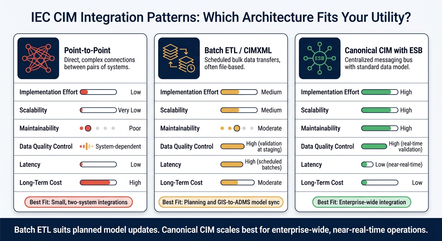
IEC CIM Integration Patterns: Point-to-Point vs Batch ETL vs Canonical CIM
Once the model is clean, the next step is deciding how it moves between systems. That choice affects build effort, scale, and what you'll keep paying to support later.
Canonical CIM Model With ESB, Services, and Message Mediation
The canonical CIM pattern uses IEC CIM as the shared meaning layer across systems. An Enterprise Service Bus (ESB) manages routing, protocol conversion, and transformation between systems. In plain English, the ESB acts like a traffic cop. Even systems that aren't CIM-native can still exchange data through it.
The big upside is lower coupling. If a utility swaps out its AMI platform, it only has to update that system's mapping to CIM. The rest of the connected systems can stay as they are.
This pattern is a good fit for near-real-time use cases like outage alerts, switch status updates, and meter readings. It supports event-driven messaging through IEC 61968-9, so downstream systems such as OMS and ADMS can get updates without waiting for a full model export. That makes it a solid option for enterprise integration where you want shared data flows without a tangle of point-to-point links.
Batch ETL, CIMXML Exchanges, and GIS-to-ADMS Synchronization
For bulk transfers that don't need real-time updates, batch ETL with CIMXML is a practical option. CIMXML, defined in IEC 61970-552, uses RDF to describe relationships between electrical components. For example, it can show which switch connects to which terminal or how transformer windings are set up. It is used widely in Europe, including by ENTSO-E, for regional grid stability studies and staged data integration.
The most common use case is GIS-to-ADMS synchronization. The data is exported as a CIMXML file, checked in a staging area, and then loaded into the ADMS. For large distribution networks, a full model export can take hours. That creates a gap where field changes have not yet shown up in the operational model. If a team needs tighter sync, incremental CIMXML updates can help by sending only the changes since the last sync. The tradeoff is latency, since validation and batch schedules slow down the handoff.
Point-to-Point, ETL, and Canonical CIM Integration: A Comparison
Point-to-point connections seem simple at first: two systems and one custom interface. Easy enough. But that simplicity doesn't last. As utilities add GIS, ADMS, AMI, and asset systems, those one-off links become tough to govern. They don't scale well, and maintenance grows fast as more systems come online. For long-lived programs, point-to-point usually turns into a mess.
| Feature | Point-to-Point | Batch ETL (CIMXML) | Canonical CIM (ESB) |
|---|---|---|---|
| Implementation Effort | Low | Medium | High |
| Scalability | Very Low (interfaces grow as systems are added) | Medium | High (hub-and-spoke) |
| Maintainability | Poor (hard-coded logic) | Moderate (script-based) | High (centralized mapping) |
| Data Quality Control | System-dependent | High (validation at staging) | High (real-time validation) |
| Latency | Low | High (scheduled batches) | Low (near-real-time) |
| Long-Term Cost | High (maintenance debt) | Moderate | Low (reduced integration cost) |
| Best Fit | Small, two-system integrations | Planning and GIS-to-ADMS model sync | Enterprise-wide integration |
Batch ETL works well for planning data and scheduled model updates. Canonical CIM with middleware makes more sense when the integration must scale, stay easier to support, or handle near-real-time operations.
What Electrical Buyers and Project Teams Should Take From These Findings
CIM data quality starts before commissioning. That’s the part teams often learn the hard way. Integration choices can look solid on paper, but they fall apart fast when the source data is messy. In many cases, procurement files and contractor records decide whether equipment moves cleanly across GIS, ADMS, and EMS.
Capture Equipment Data for Clean CIM Exchange
Assign a persistent mRID during procurement, not after installation. If you wait until the equipment is already in the field, you’re asking for avoidable cleanup work later.
Procurement specs should also require Terminal and ConnectivityNode definitions. Without them, equipment may get logged as a standalone asset instead of being modeled the right way in network topology.
| Equipment Type | Key Data to Capture at Procurement |
|---|---|
| Transformer | Rated MVA, voltage ratio (kV), impedance (R, X), vector group, tap positions |
| Breaker / Switch | Rated current (A), breaking capacity, normal status (open/closed), operating time |
| Cables / Lines | Resistance, reactance, susceptance, length (feet/miles), thermal limits |
| Meters | UsagePoint, ReadingType, unit of measure (Wh, VARh), flow direction, multiplier, phase info, accuracy class |
Also record manufacturer, model, serial number, and installation date in machine-readable form.
That kind of clean procurement data cuts schema errors, connectivity gaps, and identifier mismatches before validation even begins.
Use U.S. units at the source, then define the CIM SI conversion inside the data model. That helps prevent scaling mistakes. And don’t settle for PDF-only submittals. Require XML or JSON, plus high-resolution nameplate photos for field checks before energization.
Of course, gathering the right fields is only half the job. Suppliers still need to send that data in a format your systems can use.
Use Procurement and Project Workflows That Reduce Downstream Mapping Errors
Most CIM errors trace back to two things: specs that skip model-exchange needs and field records that don’t match digital records.
Add a CIM data-delivery clause to vendor contracts. Also require structured data that matches the target CIM profile. It’s also smart to separate the physical asset from its electrical function in procurement records, so asset systems and power-system models don’t drift apart.
For sourcing and recordkeeping, a centralized marketplace can make equipment review easier. Electrical Trader can support this workflow by centralizing new and used electrical components and power distribution equipment for buyers and project teams.
Conclusion: Key Lessons From IEC CIM Field Use
CIM works best when equipment data is complete, structured, and validated before it reaches the integration layer. The lesson here is pretty simple: assign identifiers early, require structured vendor data, validate before handoff, and plan for clean model exchange from the start.
FAQs
When should utilities assign mRIDs?
Utilities should assign mRIDs early in system planning or integration. That gives each asset and function a single, persistent identity inside the CIM framework.
Why does that matter? Because connected systems and stakeholders need a steady way to point to the same piece of equipment over time. With mRIDs in place from the start, teams can reference and track specific assets with less confusion, better data lineage, and more dependable grid operations.
It also helps semantic interoperability. In plain English, different systems can “talk about” the same equipment and mean the same thing.
How is CGMES different from IEC 61968?
Both sit under the Common Information Model framework, but they do different jobs.
IEC 61968 sets the standard for interfaces between utility systems. The goal is to support distribution business processes and help separate applications work together without a lot of friction.
CGMES, on the other hand, is a specific CIM-based profile built for exchanging large-scale power system models between transmission system operators. It uses precise semantic definitions so grid models stay reliable, especially when data moves across borders.
Which system should be the source of truth?
Define the source of truth with clear governance before you map data across systems. Spell out which system owns commands, setpoints, alarms, and schedules. That step helps prevent stale values, scaling errors, and write conflicts.
Set ownership early. Then use read-only verification before you turn on write-enabled points. It’s a simple way to protect data integrity and avoid command clashes.





