
IEC 60664-1 Explained: Insulation Standards
IEC 60664-1 is an international standard for insulation coordination in low-voltage electrical systems (up to 1,000 V AC or 1,500 V DC). It defines clearances (air gaps), creepage distances (surface paths), and solid insulation to prevent electrical failures, shocks, or fires. The standard also accounts for environmental factors like altitude and pollution levels, ensuring safe operation in various conditions.
Key points include:
- Voltage & Frequency Coverage: Equipment up to 1,000 V AC, 1,500 V DC, and 30 kHz.
- Altitude: Applicable up to 2,000 meters; altitude correction factors are provided for higher elevations.
- Overvoltage Categories: Four categories (I-IV) define impulse voltage ratings based on equipment type.
- Pollution Degrees: Four levels (PD 1-4) address environmental contamination, affecting creepage distances.
- Clearances & Creepage: Specifies minimum distances to prevent arcing and tracking, influenced by voltage, pollution degree, and material properties.
- Insulation Types: Functional, basic, supplementary, double, and reinforced insulation, each with specific safety requirements.
The 2020 update introduced flowcharts to simplify clearance and creepage calculations and included 1,500 V DC in its technical tables. This standard is crucial for designing safe and reliable electrical systems in industrial, residential, and outdoor environments.
Creepage vs Clearance (12/24/40.5kV): IEC 60664-1 Tables + Altitude & Pollution Rules
sbb-itb-501186b
Equipment and Conditions Covered by IEC 60664-1
IEC 60664-1 sets clear guidelines for voltage, frequency, and environmental conditions to ensure reliable insulation coordination under various scenarios.
Voltage and Frequency Requirements
This standard focuses on low-voltage equipment operating at up to 1,000 V AC and 1,500 V DC. It also accommodates frequencies up to 30 kHz, covering traditional 50/60 Hz systems as well as modern technologies like switching power supplies and variable-frequency drives. Notably, the 2020 update added the 1,500 V DC limit to its dimensioning tables, reflecting the rise of DC systems. Even equipment functioning at extra-low voltages - Class III devices (≤25 V AC or ≤60 V DC) - falls under its scope, though such systems typically demand less rigorous insulation measures. For higher voltages, up to 2,000 V AC and 3,000 V DC, additional guidance is outlined in IEC TS 62993.
Beyond electrical specifications, the standard takes environmental conditions into account when determining insulation requirements.
Altitude Limits and Environmental Factors
IEC 60664-1 applies to equipment used at altitudes of up to 2,000 meters (approximately 6,560 feet) above sea level. At greater heights, the reduced air density lowers dielectric strength, increasing the risk of arcing. To mitigate this, the 2020 edition includes altitude correction factors (refer to Table F.10), which help adjust clearance distances as necessary. However, the standard excludes scenarios involving liquid insulation, compressed air, or gases other than air. Additionally, its clearance specifications do not cover environments with ionized gases, leaving such cases to be addressed by the appropriate technical committees.
How Insulation Coordination Works
IEC 60664-1 Overvoltage Categories and Pollution Degrees Guide
Insulation coordination involves selecting the right insulation levels to guard against overvoltages and environmental pollution, ultimately preventing arcing, equipment damage, or electric shock. The process is guided by IEC 60664-1, which defines overvoltage categories and pollution degrees. These parameters are used to calculate the minimum clearances and creepage distances needed for safe operation. Below, we’ll break down the key elements of this process.
Overvoltage Categories 1-4 and Impulse Withstand Voltages
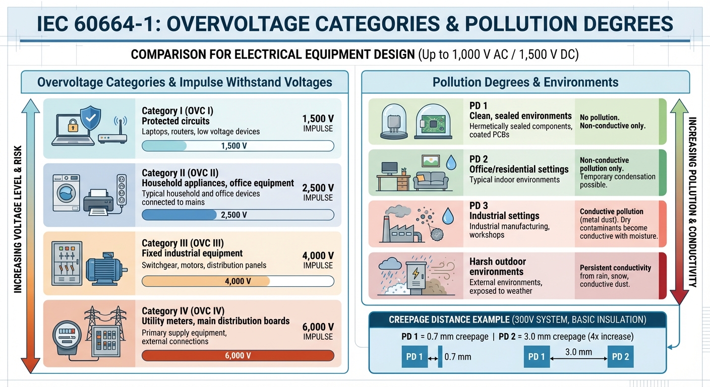
Electrical equipment is classified into four overvoltage categories (OVC I through IV) based on its position within the electrical distribution system. Each category corresponds to a specific impulse voltage rating - the maximum peak voltage the insulation must handle without failing. Here’s how the categories are defined:
- Category I: For devices like laptops and routers operating on protected circuits, the insulation must withstand impulse voltages of 1,500 V.
- Category II: Covers household appliances and office equipment, requiring insulation capable of handling 2,500 V.
- Category III: Applies to fixed industrial equipment like switchgear and motors, with a 4,000 V impulse rating.
- Category IV: Includes utility meters and main distribution boards, where transient overvoltages are highest, requiring 6,000 V.
These impulse withstand voltages determine the minimum clearance distance through air between conductive parts. The type of electric field also matters. For example, sharp edges creating an inhomogeneous field require 1.5 mm of clearance for a 2.5 kV impulse, while a homogeneous field needs only 0.6 mm.
"By accurately selecting the right pollution degree and overvoltage category, engineers can optimize insulation coordination and enhance system reliability".
While impulse voltages govern air clearances, environmental pollution levels play a key role in determining creepage distances.
Understanding Pollution Degrees
Pollution degrees are used alongside overvoltage categories to assess environmental contamination and adjust creepage distance requirements. These degrees (PD 1 through 4) are defined as follows:
- PD 1: Clean, sealed environments where insulation is unaffected by pollution - examples include hermetically sealed components or coated PCBs.
- PD 2: Found in typical office or residential settings, where only non-conductive pollution is present. Temporary conductivity, such as from condensation, may occur.
- PD 3: Common in industrial settings with conductive pollution, such as metal dust or dry contaminants that become conductive when exposed to moisture.
- PD 4: Harsh outdoor environments with persistent conductivity from rain, snow, or conductive dust.
The pollution degree directly impacts the required creepage distance, which is the shortest path along an insulating surface between conductive parts. For instance, in a 300 V system with basic insulation, PD 1 requires a creepage distance of just 0.7 mm. However, PD 2 increases this to 3.0 mm - over four times as much. Surface contamination heightens the risk of creepage, so engineers must carefully evaluate the "micro-environment" around the insulation. A sealed enclosure in an industrial setting (macro-environment PD 3) might create a cleaner internal micro-environment equivalent to PD 1, allowing for reduced safety distances.
Clearances, Creepage Distances, and Insulation Types
Once you've defined the overvoltage category and pollution degree, the next step is translating these into specific physical dimensions. This involves refining calculations based on IEC 60664-1 to make them practical for design work. Two key concepts come into play here: clearance (the direct air gap between conductive parts) and creepage (the path along the surface of insulation). While both aim to prevent arcing and tracking, the methods for calculating them differ.
Minimum Clearances Between Conductive Parts
Clearance requirements hinge on factors like the rated impulse voltage (tied to the overvoltage category), the shape and layout of electrodes, and altitude. The type of electric field - whether homogeneous (e.g., parallel conductors) or inhomogeneous (sharp edges) - also plays a crucial role. For instance, at an impulse voltage of 2.5 kV, an inhomogeneous field demands a clearance of 1.5 mm, compared to just 0.6 mm for a homogeneous field. This distinction is critical when designing compact PCBs or enclosures, as avoiding sharp edges can significantly reduce the clearance needed.
These clearance values are valid for altitudes up to 2,000 m. For designs above this height, you’ll need to apply altitude correction factors since air breakdown voltage decreases as the air thins. For a detailed process, refer to the flowchart in Annex G of the IEC 60664-1:2020 edition.
Once clearances are established, the focus shifts to calculating creepage distances, which depend on voltage, pollution degree, and material properties.
How to Calculate Creepage Distances
Creepage distance is influenced by the RMS or DC working voltage, the pollution degree, and the material's resistance to tracking, quantified by its Comparative Tracking Index (CTI). Materials are categorized from Group I to Group IIIb, with Group I (CTI ≥ 600) allowing for the shortest creepage distances and Group IIIb (CTI 100–174) requiring the longest. For example, at 250 V in Pollution Degree 2 with a Group I material, the required creepage is 1.8 mm. However, in Pollution Degree 3, this increases to 3.8 mm.
When PCB space is tight, adding 1 mm slots can double the creepage path by twice the slot depth. Additionally, applying a conformal coating can lower the pollution degree (e.g., from PD 2 to PD 1), which reduces the required creepage distance. If the working voltage falls between the values listed in IEC 60664-1 tables, use linear interpolation to calculate the exact creepage distance and round up to the nearest 0.1 mm.
Once clearances and creepage distances are determined, the next step is selecting the right insulation type to ensure safety and compliance.
Insulation Types and Testing Requirements
After calculating clearances and creepage, it's essential to choose the appropriate insulation type in line with IEC 60664-1 standards. The standard outlines five insulation types, each with specific testing protocols:
- Functional insulation: Ensures proper operation of the equipment but doesn’t protect against electric shock.
- Basic insulation: Protects against electric shock and must pass impulse voltage tests.
- Supplementary insulation: An extra layer added to basic insulation as a backup.
- Double insulation: Combines basic and supplementary insulation in one system.
- Reinforced insulation: A single system offering the same protection as double insulation, typically requiring double the creepage distance of basic insulation.
Testing methods include impulse voltage tests to confirm that clearances can handle transient overvoltages, partial discharge tests (see Annex C) to ensure no internal discharges occur in solid insulation, and mechanical tests where components endure a steady 10 N force to verify that minimum distances hold under stress. A practical guideline for IT equipment is to maintain 8 mm of creepage between primary and secondary circuits and 4 mm between primary and ground. This approach provides a 95% probability of passing compliance tests.
Why Compliance with IEC 60664-1 Matters
IEC 60664-1 plays a crucial role in preventing electric shock, overvoltages, and insulation failures in low-voltage systems. By adhering to its clearance and creepage distance requirements, designers can significantly lower the risk of electrical arc ignition, which is a key factor in minimizing arc flash incidents. The standard also provides a consistent framework for electrical design, regardless of the installation environment.
"Complying to the standard and implementing its guidelines help ensure that LV electrical switchboards and panels work like they should. That improves electrical safety and lessens the chance for a lack of service continuity, thereby reducing downtime and associated costs."
– Schneider Electric
How the Standard Applies to Breakers and Transformers
Circuit breakers and transformers are essential components in power distribution systems, and IEC 60664-1 has a direct impact on their design. As a foundational safety publication under IEC Guide 104, it establishes the baseline rules for product-specific standards, such as IEC 61558-1 for transformers and IEC 62271-37-013 for circuit breakers. Third-party certifications can confirm that suppliers are adhering to the standard, reducing the need for internal validation processes.
For instance, in an industrial setup with a nominal voltage of 1,000 V and overvoltage category III, the rated impulse voltage is 8,000 V. This requires a minimum clearance of 8 mm (approximately 0.31 in) in a pollution degree 3 environment. Panel builders should regularly inspect these clearances and creepage distances, especially after fault events, to ensure ongoing compliance. This careful adherence to standards helps protect sensitive equipment, even in tough environments.
Maintaining Safety in Polluted Environments
IEC 60664-1 extends its safety measures to equipment operating in polluted environments. Industrial settings, often classified as pollution degree 3, expose insulation to contaminants that can degrade its performance. The standard addresses this issue by specifying minimum creepage distances based on the pollution degree, reducing the risk of electrical tracking along insulating surfaces. This is particularly critical for equipment in industrial facilities or outdoor substations where environmental conditions can be harsh.
The standard defines four pollution degrees, ranging from 1 to 4, to ensure insulation integrity as conditions worsen. Manufacturers are advised to verify that clearances and creepage distances remain compliant, especially after short-circuit testing. This helps minimize risks such as connection damage or dielectric failure, which could lead to unexpected outages.
Supporting Overvoltage Protection Systems
Overvoltage protection is a key consideration, addressing both lightning strikes and routine equipment switching. By defining impulse voltage ratings, IEC 60664-1 ensures that insulation coordination can handle transient voltage stresses effectively. The standard outlines rated impulse voltage (Uimp) requirements across overvoltage categories I through IV, ensuring equipment can withstand these challenges.
"If the design distances are respected, the panel builder gets the guaranty of the performances to almost all types of over voltages and installation environmental constraints."
– Schneider Electric Blog
For designers, the 2020 edition of the standard includes helpful flowcharts in Annex G (for clearances) and Annex H (for creepage distances). These tools simplify the process of aligning overvoltage protection strategies with equipment dimensions, reducing the risk of insulation failures during transient events.
Conclusion
IEC 60664-1 provides a standardized approach to designing, installing, and operating safe electrical systems. By defining specific requirements for clearances, creepage distances, and insulation, it plays a critical role in minimizing electrical hazards. This standard is particularly applicable to equipment operating at voltages up to 1,000 V AC or 1,500 V DC and frequencies up to 30 kHz.
"The main purpose of IEC 60664-1 is to establish uniformity in the design, installation, and operation of electrical systems."
– IEC Equipment
As a basic safety publication under IEC Guide 104, the standard outlines principles that help technical committees align safety requirements across various electrical products. These guidelines ensure that products like circuit breakers and transformers operate reliably under real-world conditions. Whether you're assessing power distribution equipment or reviewing specifications, applying concepts like overvoltage categories, pollution degrees, and altitude corrections is key to meeting regulatory safety standards.
The 2020 edition introduced helpful flowcharts (Annex G and H) to streamline the process of calculating clearances and creepage distances. For professionals involved in sourcing components or evaluating equipment, understanding the principles laid out in IEC 60664-1 is essential. It ensures that products meet the required safety benchmarks for specific applications and environments.
Adhering to IEC 60664-1 not only safeguards systems and users from avoidable electrical failures but also supports service continuity across a wide range of operating conditions.
FAQs
How do I choose the right overvoltage category for my equipment?
Selecting the appropriate overvoltage category under IEC 60664-1 involves evaluating the equipment's environment and the level of transient overvoltages it might encounter. These categories classify the severity of overvoltages, ranging from Category I (low-energy circuits) to Category IV (direct connections to the primary power grid).
- Category I: Applies to circuits with limited transient energy, such as those found in protected or low-energy environments.
- Category II: Common for household appliances and portable tools connected to standard outlets.
- Category III: Designed for equipment in fixed installations, like industrial machinery or distribution panels.
- Category IV: Reserved for equipment directly connected to the primary power supply, such as utility meters or main service panels.
To ensure safety, it's crucial that insulation and clearance distances align with the chosen category's requirements.
How do I determine the pollution degree for my actual installation environment?
To figure out the pollution level in your installation environment, consider factors like dust, humidity, chemicals, or conductive materials. The IEC 60664-1 standard outlines four pollution degrees:
- Degree 1: Environments that are clean and dry.
- Degree 2: Locations with occasional condensation, such as homes or offices.
- Degree 3: Areas with conductive pollution, common in industrial settings.
- Degree 4: Conditions with persistent conductivity, like outdoor spaces.
Select the appropriate degree based on your environment to maintain proper insulation and safety.
When should I use reinforced insulation instead of basic or double insulation?
Reinforced insulation is crucial in settings where higher safety margins are a must. This includes environments with an increased risk of electric shock or situations where extra safeguards against insulation failure are essential. Safety standards like IEC 60664-1 detail the conditions under which reinforced insulation is required to provide sufficient protection.