
How Transient Response Impacts Voltage Regulator Performance
If a regulator can’t hold voltage during a sudden load step, the rest of the spec sheet doesn’t matter much.
I’d boil the article down to this: when I compare voltage regulators, I look first at voltage dip/spike, recovery time, and whether the output stays inside the allowed ripple band during load and line changes. Research on buck regulators, VRMs, and DC-DC converters shows that poor transient response can lead to logic faults, resets, extra heat, and more stress on parts - especially on processor power rails.
Here’s the short version:
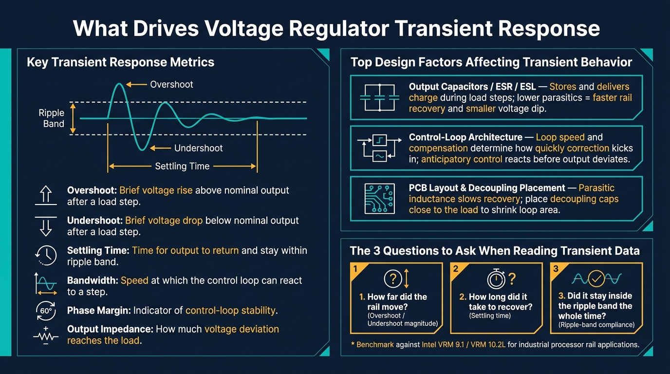
- The main metrics are: overshoot, undershoot, settling time, bandwidth, phase margin, and output impedance
- Load transients matter most for digital rails because processor current can change very fast
- Good transient response often means less voltage error, less dependence on large capacitor banks, and lower stress on the power stage
- The biggest design factors are: output capacitors, ESR/ESL, control-loop tuning, PCB parasitics, and decoupling placement
- For sourcing or replacement, I wouldn’t stop at voltage/current ratings; I’d also check test conditions, control method, capacitor assumptions, and ripple-band compliance
- Benchmark specs such as Intel VRM 9.1 and 10.2L are often used to judge whether a design can hold regulation during fast current steps
A simple way to read transient data is this: how far did the rail move, how long did it take to come back, and did it stay inside spec the whole time? If I can answer those three questions, I usually have a much better read on regulator performance than from nominal ratings alone.
The rest of the piece backs up that point with research findings and shows what to check before choosing a part for industrial, commercial, or construction equipment.
KEMET Webinar | Optimizing Load Transients in Regulators
sbb-itb-501186b
Core Transient Response Metrics Used in Research
Researchers tend to look at the same small group of measurements when they compare how a voltage regulator reacts to sudden load changes. The focus is pretty simple: how far the waveform moves and how fast it comes back.
Overshoot, Undershoot, and Settling Time
When load current shifts all at once, the output voltage may jump above the target or dip below it before the regulator pulls it back into range. Overshoot is the brief rise above the nominal output. Undershoot is the brief drop below it.
Settling time is the amount of time the output needs to return to the specified ripple band and stay there after the step.
Taken together, these numbers show two things: the size of the voltage error and the speed of recovery after a load step. That’s why they show up so often in research papers.
Researchers also look at bandwidth, phase margin, and output impedance. These metrics help explain how fast the control loop reacts to a step and how much of that voltage deviation reaches the load before the system settles.
"Fast load transient response and tight regulation are two strict specifications of dc–dc converters, called voltage regulator modules (VRMs), to power desktops and microprocessors." - IET Power Electronics
Load Transients in Digital Rails
A load transient is a sudden current step from the load. A line transient, by contrast, comes from a change in input voltage.
In VRMs, load transients usually get more attention. The reason is straightforward: digital loads such as microprocessors can swing current very fast while still needing the output voltage to stay inside a defined ripple band.
These metrics lead straight into the next issue: how transient behavior affects accuracy, stress, and reliability.
What Research Shows About Transient Response and Regulator Performance
Effects on Output Accuracy and Stability
When transient response is weak, a load step can shove the output voltage outside the ripple band before the control loop catches up. On the bench, that usually means more undershoot, more overshoot, and a longer settling time. Those shifts are exactly what transient metrics are meant to measure.
A useful result from IET Power Electronics looks at anticipatory control in VRMs. Instead of waiting for the output to move, anticipatory control predicts load steps and reacts ahead of time, reducing transient deviation. In turn, the output voltage stays within the ripple band during load steps.
Effects on Component Stress and Thermal Loading
Response speed also affects how hard the regulator works its own parts. Many traditional VRMs rely on large output capacitors to keep voltage inside the ripple band during load steps. With better transient response, that dependence can drop, which helps with board space and heat limits.
More stress can also increase the risk of instability, especially on tight-tolerance digital rails. That’s why transient behavior isn’t just a performance detail. It’s tied to how the regulator handles electrical and thermal strain. The next step is to separate those performance results from the design choices behind them.
Effects on System Reliability With Sensitive Loads
For VRMs that power desktops and microprocessors, fast load transient response and tight regulation are both strict specs. If transient response falls short, the stability and reliability of those sensitive loads can suffer directly.
Transient response data gives a plain answer to a hard question: can the regulator keep output voltage within limits during real load steps? If one design does this better than another, the gap usually comes from the output network, control-loop design, and layout.
Design Factors That Most Affect Transient Behavior
Voltage Regulator Transient Response: Key Metrics & Design Factors
A regulator’s transient behavior comes down to a few design choices. These are the main ones behind overshoot, undershoot, and settling time.
Output Capacitors, ESR, and ESL
Output capacitance stores charge for load steps. ESR and ESL then shape how fast that stored charge can get to the rail.
Lower parasitics help the rail recover faster and cut voltage dip. In plain terms, the capacitor isn’t just there to hold charge. It also has to deliver that charge fast enough when the load suddenly asks for more current.
Better control can also reduce how much bulk capacitance you need. So instead of leaning on a big capacitor bank to absorb every load step, the regulator can do more of the work itself.
Control-Loop Architecture and Compensation Choices
Control-loop architecture and compensation decide how fast the regulator reacts to a load step. If the loop is slow, the output drifts farther before correction kicks in. If it’s tuned well, the regulator pulls the rail back sooner.
Anticipatory control cuts delay by reacting before the output moves too far from the target.
That said, a fast loop doesn’t fix everything. There’s still a hard limit: layout parasitics can slow the response even when the control scheme is strong.
PCB Layout, Decoupling Placement, and Load Profile
PCB layout adds parasitic inductance, and that inductance slows transient recovery. This is one of those details that looks small on paper but can hit hard in practice.
A simple rule helps here: place decoupling capacitors close to the load. That shrinks loop area and improves response.
Load behavior matters just as much. Loads with high current demands and high slew rates require very fast transient response from the power delivery system. In other words, you can’t judge test results in a vacuum. The load profile sets the baseline for how those transient results should be read.
How to Use Transient Response Research When Selecting Equipment
How to Read Test Conditions and Waveform Plots
Transient response depends on the load profile and board layout. So before you compare results, make sure the test conditions line up with the actual application. Focus on the load-step magnitude, slew rate, ripple band, and control topology.
| Test Condition | What It Tells You |
|---|---|
| Load Step Magnitude | Whether the regulator can handle your actual current swing and still stay inside the ripple band. |
| Slew Rate (di/dt) | How fast the load changes. This matters a lot for high-speed digital loads and industrial processors. |
| Output Voltage Ripple Band | The allowed voltage window during a transient. Tighter bands point to better regulation. |
| Control Topology | Whether the design leans on passive capacitance or uses active transient control. |
When you read waveform plots, look at one thing first: does the output stay inside the ripple band during the transient? If the trace moves outside that band, even for a moment, the regulator is not meeting spec for that load condition.
That’s why test conditions matter so much. Published plots can help with a buying decision, but only if the setup matches the job you need the part to do.
Applying Transient Data to Sourcing and Replacement Decisions
If you're sourcing a replacement regulator, nominal voltage and current ratings don't tell the whole story. Two parts can share the same ratings and still behave very differently during a transient.
Start by identifying the original control method: hysteretic, PWM-based, or anticipatory. Then check whether the published transient results depend on bulk capacitance or on active transient control. This part is easy to miss, and it can bite you later. A swap between designs built around high-ESR electrolytics and low-ESR ceramics can lead to instability or slow recovery.
For industrial computing use cases, it also helps to check transient specs against Intel VRM 9.1 or VRM 10.2L. These guidelines give you benchmark targets for DC-DC converter design and transient performance requirements.
Once you understand the test conditions and the control topology, transient data stops being just a chart in a datasheet. It becomes a solid way to compare parts before sourcing or replacing a regulator.
Conclusion: Key Transient Response Takeaways
Transient response is one of the clearest signs of how a voltage regulator will behave in the field. For sourcing and replacement work, put documented transient performance first - ripple band compliance, control topology, and capacitor dependencies - not just nominal ratings. Match the transient data to the actual load profile before you buy or replace a regulator.
FAQs
Why does transient response matter more than nominal ratings?
Transient response matters more than nominal ratings because it shows how fast and how well a voltage regulator reacts when the load changes all of a sudden.
That matters in practice. A strong transient response helps keep output voltage swings small, which can prevent device malfunctions or even outright failures.
How can I tell if a regulator will stay in spec during load steps?
Check its load transient response. In plain English, that means looking at how the regulator reacts when the load current jumps all of a sudden.
This behavior depends on things like the output capacitor value and how fast the feedback loop responds.
A larger COUT and a well-tuned feedback network can help the regulator hold the output voltage within spec during sharp load changes.
What design choices best improve transient response?
The main design choices are:
- Increase control-loop bandwidth
- Use fast auxiliary converters or resonant switch-capacitor circuits
- Add output or phase-compensation capacitors
The goal is simple: cut voltage deviation during load changes.
When the load shifts, the power stage has to react fast. A higher control-loop bandwidth helps the regulator correct the output sooner. Fast auxiliary converters and resonant switch-capacitor circuits can step in during those brief transition moments, which helps smooth the response. Output or phase-compensation capacitors also help by buffering the system while the control loop catches up.


