
How Grain-Oriented Silicon Steel Reduces Core Loss
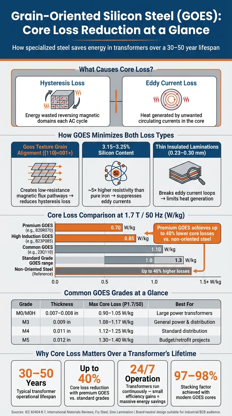
Grain-oriented silicon steel (GOES) is a specialized material used in transformer cores to minimize energy losses, known as core loss. These losses, which occur continuously even when transformers are idle, are caused by two factors: hysteresis loss (energy used to reverse magnetic domains) and eddy current loss (heat generated by circulating currents within the core). GOES reduces both by aligning its grain structure to create efficient magnetic pathways and using thin, insulated laminations to limit eddy currents.
Key takeaways:
- GOES reduces hysteresis loss with its aligned grains, making magnetization more energy-efficient.
- Its silicon content improves electrical resistivity, cutting down on eddy current loss.
- Thin laminations (0.23–0.30 mm) further reduce energy waste by disrupting current loops.
- Compared to non-oriented steel, GOES achieves up to 40% lower core losses, saving energy and lowering long-term costs.
Grain-Oriented Silicon Steel vs. Standard Steel: Core Loss & Key Properties
Properties and Structure of Grain-Oriented Silicon Steel
Silicon Content and Electrical Resistivity
Silicon plays a crucial role in grain-oriented electrical steel (GOES), with a content range of 3.15%–3.25% that significantly improves electrical resistivity.
"Electrical steels, also known as silicon steels, play an essential role in the generation, transmission, and use of electricity." - International Materials Reviews
At this level, the steel's resistivity is about five times higher than pure iron, which helps suppress eddy currents that would otherwise waste energy as heat. Additionally, silicon reduces magnetostriction - essentially the steel's tendency to vibrate under magnetic stress - thereby cutting mechanical vibration losses that add to overall core loss.
While increasing silicon content beyond 3.2% can further enhance resistivity, it also makes the steel brittle and unsuitable for efficient cold-rolling. Research into 6.5% silicon steel has shown promising results, such as near-zero magnetostriction and lower core losses, making it ideal for high-frequency applications. However, manufacturing difficulties have kept this material from being widely adopted in industrial transformer production.
The next step in boosting GOES performance lies in the precise alignment of its grains.
Grain Orientation and Magnetic Properties
What sets GOES apart from standard silicon steel is its engineered grain structure. During production, a carefully controlled rolling and annealing process aligns the steel's crystal grains in a specific pattern known as the Goss texture ({110}<001>).
"The <001> orientation of the Goss texture aligned with the rolling direction is the most easily magnetized direction, effectively enhancing the magnetic properties." - International Journal of Minerals, Metallurgy and Materials
This unique grain alignment allows the magnetic flux in transformer cores to flow along a low-resistance path during each AC cycle. As a result, less energy is required to reverse the magnetic domains, which reduces hysteresis losses. Premium grades of GOES achieve core losses as low as 0.80 watts per kilogram at 1.7 Tesla and 50 Hz, outperforming standard grades that typically range between 1.0 and 1.3 W/kg.
Lamination Thickness and Its Effect on Core Loss
Beyond the material's intrinsic properties, the design of laminations further reduces core loss. Without thin laminations, eddy currents would cause significant energy losses. To counter this, GOES is sliced into thin, insulated laminations that are stacked to form the transformer core.
For standard power transformers, lamination thickness usually falls between 0.23 and 0.30 mm. Thinner laminations shorten the path for eddy currents, increasing resistance and lowering energy losses. High-frequency or compact designs often use ultra-thin gauges - ranging from 0.025 to 0.10 mm - to achieve even tighter control over losses. The table below highlights the relationship between grade type, thickness, and core loss performance:
| Grade Type | Typical Thickness | Max Core Loss (at 1.7T/50Hz) |
|---|---|---|
| Common (e.g., 23Q110) | 0.23 mm | 1.10 W/kg |
| High Induction (e.g., B23P085) | 0.23 mm | 0.85 W/kg |
| Domain Refined/Laser (e.g., B20R070) | 0.20 mm | 0.70 W/kg |
However, thinner laminations come with trade-offs. They are more expensive to produce and can weaken the mechanical strength of the core. To address this, modern GOES cores achieve a stacking factor of 97% to 98%, ensuring minimal space is wasted between layers. This careful balance between lamination thinness, insulation coating, and structural integrity has been fine-tuned by manufacturers over decades.
sbb-itb-501186b
How GOES Reduces Core Loss
Reducing Hysteresis Loss
In a transformer core, each AC cycle forces the magnetic field to reverse direction, which causes energy loss known as hysteresis loss. This loss depends on how much effort is needed to reorient the magnetic domains within the steel.
Grain-Oriented Electrical Steel (GOES) simplifies this process. Its Goss texture ({110}<001>) creates a nearly single-crystal pathway for magnetic flux along the rolling direction:
"The result is a near single-crystal pathway for magnetic flux along that direction, which dramatically reduces hysteresis and eddy-current losses when magnetized parallel to the rolling direction." - Weijunli Steel
Thanks to its well-aligned grains, GOES allows magnetic domains to shift with minimal internal friction. This reduces the material's coercivity, or the force required to flip the domains, making magnetization cycles more energy-efficient.
However, this efficiency is direction-dependent. GOES performs best when flux flows parallel to the rolling direction. When magnetized in the transverse direction, efficiency drops significantly. This is why careful core design and precise lamination orientation during assembly are so important.
Beyond reducing hysteresis loss, GOES also addresses energy loss caused by eddy currents.
Reducing Eddy Current Loss
Eddy current loss happens when alternating magnetic flux induces unwanted currents, which generate heat. GOES tackles this issue in two key ways: its ~3% silicon content increases resistivity nearly fivefold, and its thin, insulated laminations disrupt current loops to limit eddy currents.
"The silicon content and use of thin, insulated laminations limits circulating currents that typically generate heat." - Fry Steel Company
Each lamination is coated with an insulating layer, preventing currents from bridging between layers. This ensures that eddy current paths are broken, keeping energy loss under control across the transformer's operating range.
Core Design and Assembly Factors
The performance of GOES also depends on proper core design, which further reduces losses. Two critical aspects of design are joint geometry and lamination orientation.
At the corners of a transformer core, magnetic flux needs to make a 90-degree turn. If a simple butt joint is used, gaps can form where flux crosses grain boundaries, reducing efficiency. Step-lap joints solve this by staggering the lamination cuts, allowing flux to transition smoothly across multiple layers. This improves continuity, reduces localized losses, and minimizes the audible hum caused by magnetostriction.
Here’s a quick summary of the key design elements that, combined with GOES's properties, help minimize total core loss:
| Design Element | How It Reduces Core Loss |
|---|---|
| Thin laminations (typically 0.18–0.35 mm) | Shortens eddy current paths, reducing heat buildup |
| Insulating surface coating | Blocks inter-laminar current flow between stacked layers |
| Step-lap joints | Smooths flux transitions at corners, reducing localized losses |
| Flux aligned to rolling direction | Ensures magnetization follows the low-loss grain axis |
How to Use GOES in Industrial Transformers
Choosing the Right GOES Grade
Picking the right grade of Grain-Oriented Electrical Steel (GOES) for your transformer starts with understanding its target flux density range. For instance:
- Distribution transformers (≤630 kVA): Operate at 1.55–1.65 T.
- Medium power units (up to 40 MVA): Work within 1.6–1.7 T.
- Dry-type transformers: Typically range from 1.5–1.6 T.
Once you identify the flux density range, match it to a suitable GOES grade. The table below outlines common grades and their applications:
| Grade | Thickness (in.) | Typical Max Loss P1.7/50 (W/kg) | Best For |
|---|---|---|---|
| M0 / M0H | 0.007–0.008 | 0.90–1.05 | Large power transformers; strict loss limits |
| M3 | 0.009 | 1.08–1.17 | General power and distribution transformers |
| M4 | 0.011 | 1.12–1.25 | Standard distribution; cost-sensitive designs |
| M5 | 0.012 | 1.30–1.40 | Retrofits; budget-driven projects |
It’s worth noting that M-grade labels are broad classifications and not precise indicators. Modern standards like IEC 60404-8-7 provide more accurate descriptions. For example, M108-23 specifies a maximum loss of 1.08 W/kg at 1.7 T with a nominal thickness of 0.23 mm.
"The 'M-grade' label is only a window. Modern catalogues put typical 0.23 mm 'M3' around 0.7–0.8 W/kg at 1.5 T and ~1.08–1.17 W/kg at 1.7 T, depending on mill and generation of steel." - Sino Lamination
Although higher-grade steels like Hi-B may come with a higher initial cost, they can be a smart investment when no-load loss penalties are a concern or when compact core designs are required.
After selecting the right grade, focus on precise assembly to maintain performance.
Core Assembly Best Practices
The efficiency of GOES can be easily compromised by poor assembly. To reduce core loss, it’s critical to handle and assemble the material carefully, preserving its grain alignment. Mechanical stress is a key factor to watch out for - processes like punching and shearing can create deformed edge zones that disrupt grain alignment and increase losses. To counter this, stress-relief annealing at 750–800 °C (1,380–1,470 °F) is often necessary to restore the material’s properties.
Clamping pressure during assembly is another important consideration. Uneven pressure can create localized stress, misaligning the magnetic flux path. As Charlie Cheney, Senior Application Engineer at Sino, puts it:
"The transformer does not care whether the extra watts came from a cheaper grade or a sloppy angle; it only knows the magnetization path it actually sees."
To ensure optimal efficiency, keep the magnetization angle at 0°, especially in high-flux regions. If you’re using laser-scribed (domain-refined) grades for added efficiency, be cautious with high-temperature annealing, as it can remove the benefits of the surface treatment. Always confirm compatibility with your supplier before combining these processes.
Reading Core Loss Data Sheets
Understanding core loss data sheets is essential for maximizing transformer performance with GOES. The two standard reference points are:
- P1.5/50: Loss at 1.5 T and 50 Hz.
- P1.7/50: Loss at 1.7 T and 50 Hz.
Keep in mind that losses measured at 50 Hz are about 0.79 times those at 60 Hz. So, if you’re working with European datasheets, you’ll need to adjust the values accordingly.
It’s also important to check whether the data reflects as-sheared or stress-relief annealed samples. Annealing can significantly reduce reported losses. Additionally, avoid designing right up to the guaranteed maximum loss values. Allow for a 10–15% margin to account for variations between production lots and measurement tolerances.
Two other critical figures to review are:
- Lamination factor: Typically between 94.5% and 97%, this shows how much of your stack height is actual steel. Assuming a 100% steel stack can lead to unexpected flux squeeze and higher losses.
- Full P(B) curve: This chart, usually spanning 1.3 T to 1.7 T or more, provides insight into how the steel performs during over-flux events - something a single guarantee point won’t reveal.
Industrial Applications and Cost Benefits of GOES
Common Applications in Industrial Transformers
Grain-Oriented Electrical Steel (GOES) is the backbone of stationary transformers across U.S. industries. Its grain alignment makes it ideal for equipment where magnetic flux flows in one consistent direction, which is the case for nearly all transformers in the electrical grid.
| Transformer Type | Typical GOES Application |
|---|---|
| Power Transformers | Large-scale grid transmission and substation cores |
| Distribution Transformers | Local voltage stepping for commercial and residential use |
| Industrial Transformers | High-capacity units for factories and data centers |
| Specialty Transformers | Rectifier transformers, autotransformers, and renewable energy plants |
| Reactor Cores | Grid stability and infrastructure equipment |
GOES offers a significant advantage over Non-Oriented Electrical Steel (NOES) by enabling lighter transformer cores. This translates into reduced material usage, simpler cooling systems, and lower installation costs. These benefits contribute to long-term operational efficiency.
Cost Savings from Lower Core Loss
Transformers typically operate for 30 to 50 years, so even small reductions in core loss can lead to substantial energy savings over time. As noted by Frontier | Winston:
"When multiplied by the mass of a transformer core and by 40 years of continuous operation, those [core loss] numbers translate into significant amounts of electricity that either reach end users or dissipate as heat within the equipment."
Lower core loss means less heat is wasted, which reduces cooling requirements and slows down insulation wear. This extends the transformer's lifespan and minimizes the chance of unexpected failures. Additionally, GOES reduces reactive power demand by lowering magnetizing current, which can cut demand charges for large-scale industrial users.
Tips for Specifying GOES in Transformer Procurement
To fully leverage the cost benefits of GOES, it's crucial to define precise specifications when procuring transformers. Avoid relying solely on grade labels like "M4" or "M3", as these can vary between manufacturers. Instead, focus on measurable and verifiable performance metrics.
Key elements to include in your procurement documentation:
- No-load loss limit: Specify a no-load loss limit of 1.08 W/kg at 1.7 T and 60 Hz. This ensures the use of a suitable GOES grade rather than leaving it to the manufacturer's discretion.
- Lamination thickness: Clearly state the required nominal thickness, such as 0.23 mm (0.009 in.), to control eddy current losses.
- Material Test Certificates (MTC): Require full loss and permeability curves from the supplier to confirm the steel meets design expectations.
Additionally, specify whether core loss measurements should be taken as-sheared or after stress-relief annealing, and include the type of insulation coating required (e.g., ASTM C-5) to maintain proper interlaminar resistance. When evaluating bids, consider the total cost of ownership, not just the upfront purchase price, to avoid unnecessary energy waste over the transformer's lifespan.
Conclusion and Key Takeaways
Summary of GOES Benefits
Grain-oriented silicon steel (GOES) plays a vital role in transformer cores. Its specialized grain structure minimizes both hysteresis and eddy current losses, resulting in transformers that operate more efficiently, stay cooler, and last longer.
The numbers back this up: premium GOES achieves losses below 0.80 W/kg at 1.7 T, compared to 1.0–1.3 W/kg for standard grades - a reduction of 20–40% over a 40-year lifespan. In contrast, using non-oriented steel leads to significantly higher core losses and heavier core weights. For industrial buyers, this translates into steeper energy bills, bulkier equipment, and the need for more complex cooling systems - expenses that far exceed any initial savings on material costs.
"Because transformers run 24/7, even small efficiency gains can save large amounts of energy annually."
Efficiency and cost savings are crucial for ensuring long-term transformer performance. When purchasing transformers, consider the total cost of ownership, not just the upfront price. Pay attention to performance specifications, confirm test certifications, and select the appropriate GOES grade to guarantee optimal efficiency and reliability. These technical advantages highlight why choosing the right supplier matters.
How Electrical Trader Can Help
The efficiency benefits of high-quality GOES directly impact operational savings and reliability. If you're in the market for transformers built with top-tier GOES, Electrical Trader provides a convenient solution. The platform offers a broad selection of new and used power distribution equipment, including 3-phase and substation transformers, giving industrial buyers a streamlined way to find equipment that meets their performance and efficiency needs. Whether you're upgrading existing systems or sourcing equipment for a new project, Electrical Trader simplifies the process by making it easy to compare options without the hassle of traditional procurement methods.
The ultimate guide to the Grain oriented Silicon Steel material to produce transformer core
FAQs
How do I choose the right GOES grade for my transformer?
When choosing the right grain-oriented electrical steel (GOES) grade, it's all about finding the right balance between core loss requirements, magnetic flux capacity, and your budget. Here's how to approach it:
- Core Loss and Efficiency: Review supplier-provided loss curves, such as P1.5/50, to understand the material's performance. If you're aiming for high efficiency, thinner grades like 0.20 mm are a good option.
- Cost Considerations: For more budget-conscious designs, thicker grades like 0.30 mm might be more suitable, as they generally cost less.
- Compatibility Factors: Pay attention to details like the lamination factor, thickness tolerances, and the coating type to ensure the material works well with your assembly process.
By weighing these factors, you can choose a GOES grade that aligns with your technical needs and financial constraints.
What core design choices can ruin GOES performance?
Grain-oriented electrical steel (GOES) achieves optimal performance when magnetized along its rolling direction. However, its efficiency drops significantly when flux paths are misaligned, particularly with magnetization angles deviating by 20–30 degrees or more. Poorly designed features like corners, joints, or T-joints exacerbate these losses. Moreover, mechanical stresses caused by issues such as improper punching, uneven clamping, or burred edges can lead to misorientation and residual stresses, further increasing core losses.
How should I read P1.5/50 and P1.7/50 loss ratings?
Grain-oriented silicon steel is often rated with values like P1.5/50 and P1.7/50, which measure energy loss in watts per kilogram (W/kg). Here's what these ratings mean:
- P1.5/50: Energy loss at a magnetic flux density of 1.5 Tesla and a frequency of 50 Hz.
- P1.7/50: Energy loss at 1.7 Tesla and the same frequency of 50 Hz.
These standardized ratings are crucial for comparing the efficiency of different materials. However, keep in mind that energy losses increase with higher flux densities. Factors like material thickness and processing methods can also influence these values, so consistent test conditions are essential for accurate comparisons.


