Guide to Testing Transformer Windings
Transformer winding testing ensures transformers operate efficiently and safely by identifying potential issues like shorted turns, open circuits, or insulation breakdown. Regular testing prevents costly failures and power outages. Here’s what you need to know:
- Why Test? Early detection of faults like loose connections or overheating can prevent transformer damage. Resistance readings should typically fall within 1-2% variance.
- Common Testing Methods: Includes DC winding resistance testing, insulation resistance (Megger) testing, transformation ratio testing, and dielectric tests.
- Safety First: Always de-energize the transformer, follow Lockout/Tagout (LOTO) procedures, and use proper PPE.
- Equipment Needed: Key tools include a digital multimeter, micro-ohmmeter, insulation resistance tester, and temperature measurement devices.
- Temperature Matters: Resistance readings must be adjusted for temperature changes to ensure accuracy.
- Demagnetization: After testing, demagnetize the transformer to prevent inrush currents and ensure reliable diagnostics.
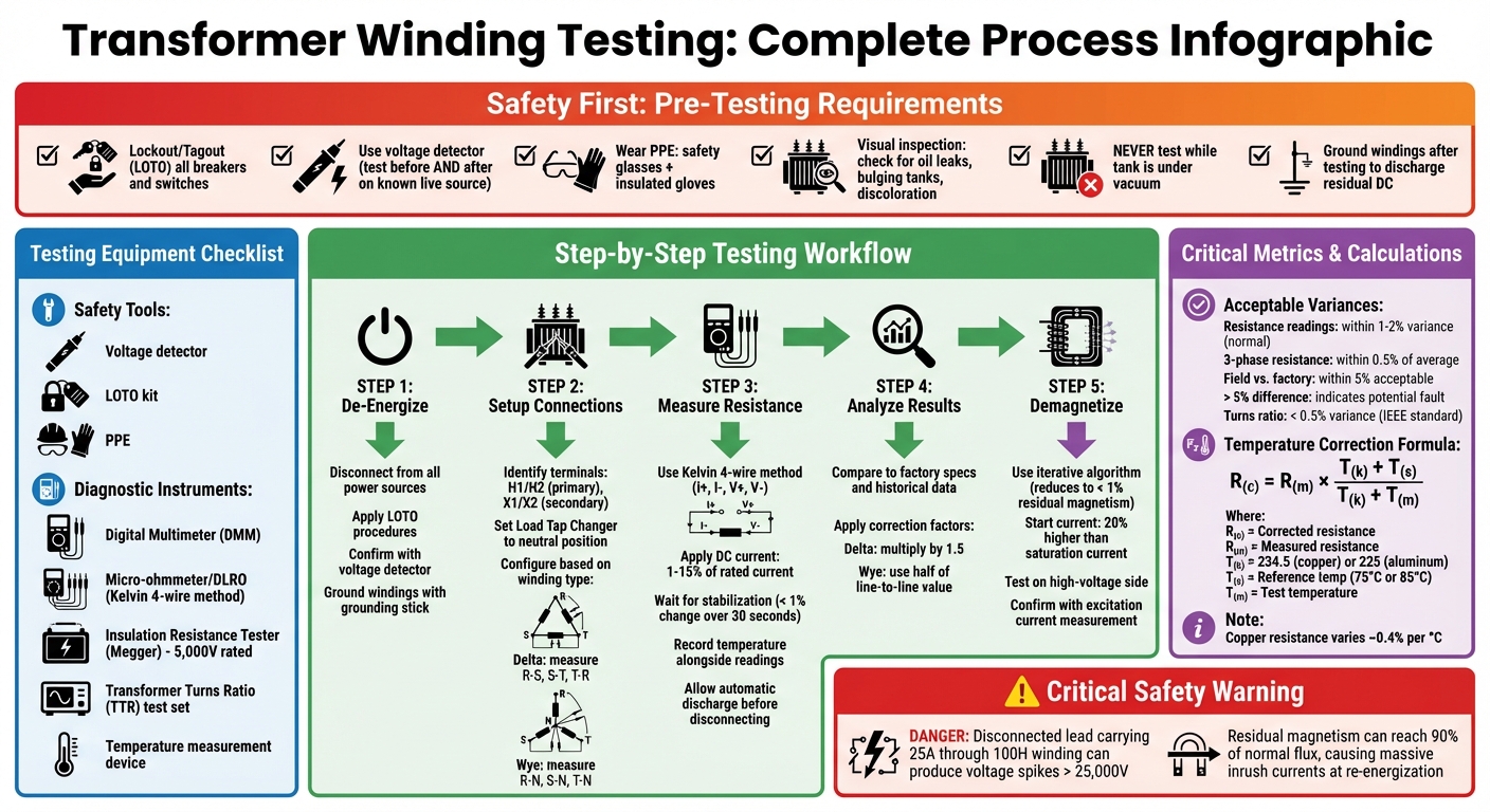
Step-by-Step Transformer Winding Testing Process and Safety Checklist
Transformer Winding Resistance Test
sbb-itb-501186b
Safety Precautions and Required Equipment
Transformer testing involves working with high voltages and stored electrical energy, making strict adherence to safety protocols an absolute must. Before beginning any tests, disconnect the transformer completely from power sources, load, and wiring to prevent any chance of accidental re-energization .
Safety Precautions Before Testing
Start by applying Lockout/Tagout (LOTO) procedures to all breakers or switches connected to the transformer. This ensures no accidental power restoration during testing. After locking out, use a voltage detector rated for the transformer’s voltage to confirm that all terminals and conductors are de-energized. To ensure the detector is functioning properly, always test it on a known live source both before and after verifying the transformer .
Proper personal protective equipment (PPE) is essential. At a minimum, wear safety glasses and insulated gloves rated for the voltage class of the transformer. Before performing any electrical testing, conduct a thorough visual inspection. Look for physical damage, oil leaks, bulging tanks, or signs of overheating, such as discolored paint or a burnt smell. Never perform tests while the transformer tank is under vacuum, as the insulation’s dielectric strength is significantly reduced under negative pressure, increasing the risks of flashover or explosion . After completing the tests, always ground the windings to discharge any residual DC current before handling or re-energizing the transformer.
Once all safety checks are complete, you can begin setting up the required testing equipment.
Testing Equipment You'll Need
For safe and effective transformer testing, you’ll need a combination of safety tools and diagnostic instruments. On the safety side, have a reliable voltage detector, a LOTO kit, and the necessary PPE. For the testing itself, here’s what you’ll need:
- A digital multimeter (DMM) for basic continuity checks.
- A micro-ohmmeter or Digital Low-Resistance Ohmmeter (DLRO) using the Kelvin Bridge four-wire method to measure winding resistance accurately by eliminating lead resistance errors .
- An insulation resistance tester (Megger), typically rated at 5,000V, to evaluate insulation quality between windings and ground. Always refer to the manufacturer’s manual for the correct DC test voltage, as some large transformers may have lower insulation levels at neutral points .
- A Transformer Turns Ratio (TTR) test set to confirm voltage ratios and identify shorted turns.
- A temperature measurement device to record winding and oil temperatures, which are critical for resistance correction calculations .
Before connecting any equipment, make sure test leads and terminals are clean and free of debris.
Preparing the Transformer for Testing
Proper preparation is key to ensuring accurate testing results and minimizing risks.
De-Energizing the Transformer
First, make sure the transformer is completely disconnected from all power sources. This means isolating it from the electrical grid as described earlier. Follow Lockout/Tagout (LOTO) procedures and confirm de-energization using a voltage detector. To ensure the detector is accurate, perform a live-dead-live test.
Once the power is disconnected, discharge any stored energy and inspect the transformer for physical issues, such as visible damage. Use a grounding stick to safely ground the windings. Omar Salah, Electrical Commissioning Manager, emphasizes:
"After the test, do not energize the transformer before earthing the windings to be sure that the windings are discharged."
Before attaching test leads, visually inspect the transformer for internal damage, such as bulging tanks or oil leaks.
After confirming the transformer is de-energized and safe, proceed to set up the testing connections.
Setting Up Testing Connections
Once safety is verified, begin configuring the testing connections. Identify the transformer’s terminal markings - H1 and H2 for the primary side, and X1 and X2 for the secondary side. For single-phase transformers, connect testing equipment between the H1 and H2 terminals on the primary and between X1 and X2 on the secondary.
For three-phase transformers, the setup depends on the winding configuration. If the windings are Delta-connected, measure resistance between the phases (R to S, S to T, and T to R). For Star (Wye) windings, measure resistance from each phase to the neutral terminal (R-N, S-N, and T-N). When testing insulation resistance between a winding and the transformer core or casing, scrape a small section of paint to ensure a solid electrical connection.
If your transformer has a Load Tap Changer (LTC), set it to the neutral position before starting. While resistance testing will involve cycling through all tap positions, starting at neutral helps protect sensitive components. Lastly, secure any disconnected cables away from the terminals using nylon rope to maintain safe clearance .
How to Test Winding Resistance Step-by-Step
Once you've set up your connections, you're ready to measure the winding resistance. The testing process will differ slightly depending on whether you're working with a single-phase transformer, dual windings, or a three-phase configuration.
Testing a Single Winding
Use the Kelvin (four-wire) method to connect your test equipment. This setup involves two leads for injecting current (I+ and I-) and two leads for measuring voltage (V+ and V-). Position the voltage leads inside the current leads to minimize measurement errors.
Choose a DC test current between 1% and 15% of the winding's rated current. This range ensures a stable reading while avoiding excessive heating of the winding, which could affect the resistance measurement. When current is applied, the transformer's iron core may saturate, causing temporary inductive drift. Wait for the reading to stabilize - this typically means no more than a 1% change over 30 seconds - before recording your measurement.
Always note the exact winding or oil temperature alongside your resistance readings. Once measurements are complete, allow the instrument to finish its automatic discharge cycle before disconnecting the leads. Megger emphasizes the importance of this step:
"If a test lead falls off or is pulled off a bushing terminal during the test, a dangerously high voltage will develop,"
highlighting that a disconnected lead carrying 25 A through a 100 H winding could produce voltage spikes exceeding 25,000 V.
Testing Dual Winding Connections
After completing the single winding test, move on to testing both windings simultaneously. Again, use the Kelvin method for each winding and ensure the injected current remains below 15% of the winding's rated current. Use jumpers to connect opposite polarities, which helps reduce the time needed for core saturation.
Wait for both readings to stabilize - this could take anywhere from a few seconds to several minutes - before recording the results. A variance of less than 2% between windings, or when compared to factory specifications, is generally acceptable. However, differences greater than 5% may indicate internal damage or connection issues.
Testing 3-Phase Winding Configurations
Testing three-phase transformers involves additional steps to check for imbalances. For Delta configurations, measure resistance between phases (H1-H2, H2-H3, H3-H1). In Wye configurations, if the neutral is accessible, measure phase-to-neutral resistance (H1-H0, H2-H0, H3-H0); otherwise, measure phase-to-phase resistance.
Here's a quick reference table for common test points and what they measure:
| Configuration | Test Points | What You're Measuring |
|---|---|---|
| 3-Phase Delta | H1-H2, H2-H3, H3-H1 | One winding in parallel with two in series |
| 3-Phase Wye (Grounded) | H1-H0, H2-H0, H3-H0 | Individual winding resistance |
| 3-Phase Wye (Ungrounded) | H1-H2, H2-H3, H3-H1 | Two windings in series |
Resistance readings between phases should typically be within 5% of each other. In some cases, standards require readings to be within 1% when comparing adjacent windings at the same tap position. As with other tests, wait for the readings to stabilize before recording them. If the transformer has tap changers, cycle through all tap positions to clean the contacts and ensure proper connections.
Reading Test Results and Adjusting for Temperature
Once you've obtained stable winding resistance readings, it's time to analyze them using standard benchmarks and adjust for temperature variations.
Understanding Resistance Tolerances
Start by comparing your measurements to factory specifications, historical field results, and readings from adjacent phases. For three-phase transformers, phase resistances should typically differ by no more than 0.5% of the average value. Slight differences of 1%–2% are generally acceptable, but anything exceeding 2%–3% could indicate potential faults.
When comparing field readings to factory data, corrected measurements within 5% of the original specifications are considered acceptable. To make these comparisons, apply the appropriate correction factor:
- For delta configurations, multiply the measured resistance by 1.5.
- For wye configurations, use half of the measured line-to-line value.
After applying the correction factor, you’ll need to adjust for temperature differences to ensure accurate comparisons.
Temperature Correction Formula
Copper windings are sensitive to temperature changes, with resistance varying approximately 0.4% per °C. To make meaningful comparisons across different testing conditions, adjust your measurements to a standard reference temperature, typically 75°C or 85°C.
Use the following formula to calculate the corrected resistance:
R₍c₎ = R₍m₎ × (T₍k₎ + T₍s₎) / (T₍k₎ + T₍m₎)
- R₍c₎: Corrected resistance
- R₍m₎: Measured resistance
- T₍k₎: Material constant (234.5 for copper, 225 for aluminum)
- T₍s₎: Reference temperature (usually 75°C or 85°C)
- T₍m₎: Test temperature
To ensure accuracy, always record the winding or oil temperature during the test. Adjusting for temperature is essential for diagnosing the condition of transformer windings and ensuring their reliable operation over time.
Demagnetizing After Testing
After measuring winding resistance, it's important to demagnetize the transformer to ensure accurate follow-up diagnostics. During DC winding resistance tests, residual magnetism often lingers in the transformer core, which can disrupt future tests. This residual magnetism can reach as high as 90% of the normal operational flux.
If not addressed, this residual magnetism can cause massive inrush currents when the transformer is re-energized. These currents can approach short-circuit levels, putting stress on the windings and potentially damaging the insulation. OMICRON experts highlight the risks:
"A too high inrush current can reduce the lifetime of a transformer due to the mechanical forces on the insulating paper".
Beyond increasing inrush currents, residual magnetism also interferes with critical tests like excitation current measurements, magnetic balance tests, and SFRA (Sweep Frequency Response Analysis), leading to skewed diagnostic results.
How to Demagnetize Transformer Windings
Modern test equipment is designed with iterative algorithms to reduce residual magnetism to below 1%. These systems work by saturating the core in both directions to determine its hysteresis parameters and then applying a decreasing AC signal to neutralize the magnetic flux. To achieve this, the starting current should be set at least 20% higher than the transformer's saturation current.
Demagnetization should typically be performed on the high-voltage side of the transformer, as the larger number of turns generates the necessary magnetic flux more efficiently. In three-phase transformers powered by a single-phase source, the middle limb usually provides the most symmetrical flux distribution. For such transformers, each phase should be demagnetized sequentially (e.g., A–N, C–N, B–N) to ensure no residual magnetism is left behind.
A practical example comes from 2014, when OMICRON electronics tested a 350 MVA power transformer. During DC resistance testing on Phase B, residual magnetism caused shifts in SFRA resonance points. The team used the CPC 100 test instrument, equipped with an iterative demagnetization algorithm, to nearly eliminate the residual magnetism. Post-demagnetization, the SFRA results confirmed success, with resonance points returning to lower frequencies.
To confirm the transformer has been effectively demagnetized, perform an excitation current measurement afterward. The results should show symmetrical and generally lower current levels compared to those recorded before demagnetization.
Conclusion
Testing transformer windings is crucial for preventing major failures and ensuring smooth power system operations. It helps uncover manufacturing flaws - like loose connections or poor solder joints - spot aging insulation, and confirm that repairs were done correctly. Skipping these checks can lead to serious issues, such as high resistance, insulation breakdown, overheating, coil burnout, or even dangerous short circuits.
Paying attention to winding tolerances is key. Keeping resistance within tight limits can reveal potential problems early. For example, IEEE standards specify that transformer turns ratio tests should not exceed a 0.5% variance, highlighting the need for precision.
Temperature correction and demagnetization also play an important role. Adjust readings to account for temperature changes, and always demagnetize after DC testing to avoid inrush currents.
Safety cannot be overstated. Always verify that the transformer is fully de-energized before testing, using a properly rated voltage detector. Additionally, maintaining detailed records - like ambient temperature and tap positions - can help track performance over time, catching subtle signs of wear before they escalate into major problems. These steps are essential for effective and reliable transformer maintenance.
FAQs
How often should I test transformer windings?
Transformer windings need regular testing, with the frequency depending on factors like their condition, usage, and maintenance routine. These tests are usually performed during planned inspections or following events like installation, relocation, or faults to confirm the transformer's performance and reliability.
What does an out-of-tolerance resistance reading usually mean?
An out-of-tolerance resistance reading often points to problems like loose or corroded connections, winding deformation, or insulation deterioration. These issues can lead to higher resistance, which may negatively impact the transformer's overall performance.
Do I need to demagnetize after DC resistance testing?
Yes, it's a good idea to demagnetize the transformer after performing DC resistance testing. This process eliminates any leftover magnetism, which could otherwise cause high inrush currents or distort diagnostic measurements. By doing so, you ensure more accurate readings and a dependable evaluation of the transformer's condition.