Generator Room Ventilation Code for Indoor Units
If an indoor generator room misses any one of these 3 air jobs, the install can fail code review or overheat under load.
I’d boil the whole topic down to this:
- You need outside air for combustion
- You need enough airflow to remove engine, radiator, and room heat
- You need radiator air and engine exhaust to leave the building without coming back in
For most indoor units, I’d check these points first:
- NFPA 110: the room has to stay within the generator maker’s max ambient limit at full load, and Level 1 rooms have tighter air-path rules
- NFPA 37: the engine room has to vent heat and vapors during use and shutdown
- IMC: covers combustion-air openings, ducts, and exhaust discharge clearances
-
Airflow math:
CFM = BTU/hr ÷ (1.08 × ΔT)
Example: 400,000 BTU/hr ÷ (1.08 × 20°F) = 18,519 CFM - Louver sizing must use net free area, not rough opening size
- Room pressure drop matters: some OEM guidance limits room vacuum to 0.5 in. H₂O
- Common temp target: if room air goes past 104°F (40°C), output may be derated
- Diesel units often need more air than similar natural gas units
If you want the short answer: size ventilation from the largest demand, verify discharge paths to outdoors, and use manufacturer data early. That is what usually drives louvers, fans, duct size, and room layout.
A fast side-by-side view:
| Check | What I’d verify |
|---|---|
| Combustion air | Outside air opening meets code and OEM airflow |
| Cooling air | Airflow handles radiator and room heat at full load |
| Louver area | Based on net free area, with screen losses included |
| Discharge path | Hot radiator air goes straight outdoors |
| Exhaust outlet | Gas-tight piping, proper clearance from openings/intakes |
| Level 1 room | Direct outdoor path or 2-hour-rated transfer path; no fire dampers in those openings |
| Added room heat | Switchgear, UPS, batteries, and load banks included in calc |
The full article then walks through the code split, airflow sizing, louver losses, discharge routing, room layouts, controls, and pre-purchase checks.
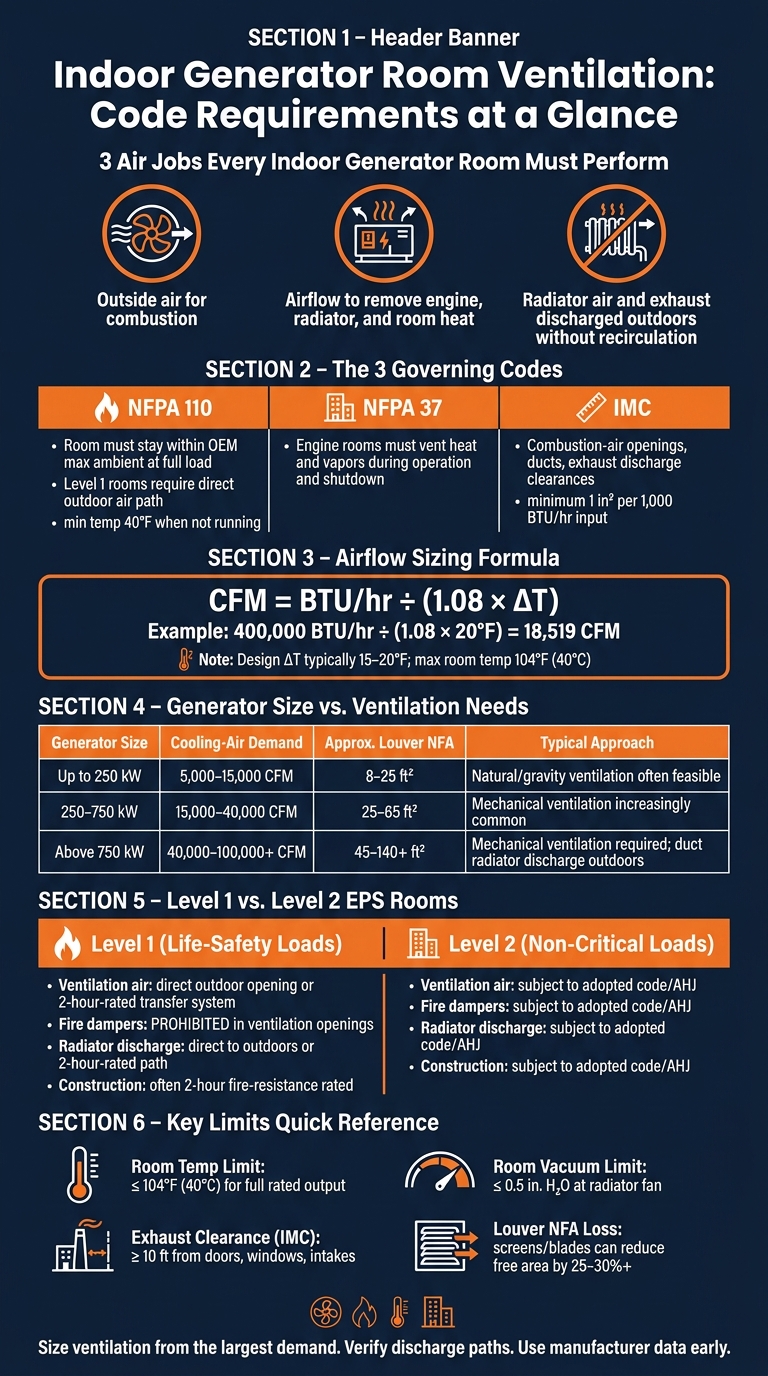
Indoor Generator Room Ventilation: Code Requirements at a Glance
Generator room Ventilation Calculation and Louver sizing using spreadsheet
sbb-itb-501186b
Code Framework for Indoor Generator Room Ventilation
Three codes shape indoor generator room ventilation.
NFPA 110 deals with room performance. NFPA 37 focuses on engine-related hazards. And the IMC covers combustion-air openings, ducts, and exhaust discharge. In plain English, those rules turn into louver sizes, airflow targets, and discharge routes in the sections that follow.
NFPA 110, NFPA 37, and IMC: What Each Code Covers
NFPA 110 requires enough ventilation and heat rejection to keep the room within the manufacturer's rated ambient temperature at full load. It also says Level 1 equipment rooms and housings must stay at 40°F or higher when the equipment is not running.
NFPA 37 says engine rooms must be ventilated so unsafe heat or vapor doesn't build up during operation or shutdown.
The IMC handles combustion-air openings, mechanical ventilation, duct construction, and exhaust discharge. It sets minimum combustion-air opening sizes, often 1 in² per 1,000 Btu/h of total input for enclosed spaces. In practice, the manufacturer's airflow data usually decides the final opening size.
Level 1 vs. Level 2 Rooms: Why the Difference Matters
NFPA 110 splits EPS installations into Level 1 and Level 2.
Level 1 systems support life-safety loads, like egress lighting, fire protection, and critical healthcare equipment. Level 2 systems serve loads that aren't as critical. That split affects something very practical: how air gets into the room and how it gets back out.
For Level 1 rooms, ventilation air must come from outdoors through either a direct outdoor opening or a 2-hour-rated transfer system, and radiator discharge air must leave the same way. Fire dampers and self-closing devices are not allowed in Level 1 ventilation openings.
| Requirement | Level 1 EPS Room | Level 2 EPS Room |
|---|---|---|
| Ventilation air source | Direct outdoor opening or 2-hour-rated transfer system | Subject to adopted code/AHJ |
| Fire dampers in ventilation openings | Prohibited | Subject to adopted code/AHJ |
| Radiator discharge path | Direct to outdoors or 2-hour-rated system | Subject to adopted code/AHJ |
| Fire-resistance rating | Higher; often 2-hour-rated construction | Subject to adopted code/AHJ |
Using Manufacturer Data as Part of Code Compliance
Pull the manufacturer submittals early. Then total the airflow and heat rejection, and check room temperature at full load.
You'll also want a thermal calculation that shows the room temperature rise at full load and confirms the ventilation system keeps temperatures below the rated maximum ambient. If the AHJ has adopted a version of NFPA 110, NFPA 37, or the IMC with local amendments, those calculations need to match the stricter rules.
Those figures set the intake and louver sizing discussed in the next section.
Combustion Air, Cooling Air, and Louver Sizing
Size intake openings based on the largest of these three needs:
- combustion air
- radiator cooling air
- room heat removal
In plain English, you size for the biggest airflow demand first. Then you verify combustion air and radiator discharge on their own. After the code side is sorted out, the job shifts to sizing openings from the manufacturer's heat-rejection data.
How to Size Air Intake Openings and Ventilation Airflow
Start with the total heat load in BTU/hr from the manufacturer's submittal. Use a design ΔT of 15–20°F unless the manufacturer calls for a tighter limit. And stay within the manufacturer's maximum ambient limit, which is often 104°F or 122°F depending on the product.
The standard formula is:
CFM = BTU/hr ÷ (1.08 × ΔT)
Here’s what that looks like in practice. If a room has a heat load of 400,000 BTU/hr and you’re aiming for a 20°F rise, you need about 18,519 CFM.
Check combustion air on its own too. Diesel engines often need about 2.5–3.5 CFM per kW at rated load. Use whichever is larger: the calculated ventilation airflow or the manufacturer’s radiator airflow.
And this is where people can get tripped up: a big opening on paper doesn’t guarantee that air will move the way you want. Louver type and pressure drop have a huge effect on actual airflow.
Net Free Area, Screens, and Louver Pressure Drop
Gross louver size is not the same as usable airflow area. What matters is net free area (NFA), or the open space left after you account for blades, frames, mullions, and screens.
A louver that measures 4 ft × 6 ft has a gross area of 24 ft², but the NFA may be only 14–17 ft² depending on the blade profile and framing.
Screens and blade choices shrink that area even more. Drainable weather blades can drop NFA to 50–65% of gross area. Bird screens with ½-inch mesh can cut NFA by another 10–15%. Fine insect screens can reduce effective free area by 20–30% or more and can also push pressure drop up hard.
That’s why insect screens should be avoided unless the fan selection already includes the added pressure drop. Use the louver manufacturer’s published NFA and pressure-drop data for each blade and screen setup. No guessing here.
Planning Table: Airflow and Louver Needs by Generator Size
| Generator Size | Typical Cooling-Air Demand | Approx. Louver NFA Needed | Typical Approach |
|---|---|---|---|
| Up to 250 kW | 5,000–15,000 CFM | 8–25 ft² per major opening | Natural (gravity) ventilation often feasible with direct wall louvers and short duct runs |
| 250–750 kW | 15,000–40,000 CFM | 25–65 ft² per opening | Natural ventilation possible at the lower end; mechanical ventilation increasingly common for interior or multi-story rooms |
| Above 750 kW | 40,000–100,000+ CFM | 45–140+ ft² per opening, often split across multiple louvers | Large units usually require mechanical ventilation; radiator discharge should be ducted directly outdoors |
Planning note: Use these ranges only for early planning; final sizing must follow manufacturer submittals and louver data.
These numbers are for early layout work only. The next check is hot-air discharge and exhaust routing, so the room doesn’t pull its own heat right back in.
Hot Air Discharge, Exhaust Routing, and Room Temperature Limits
After you size the intake air, the next step is figuring out where all that heat goes. And this is where people can get tripped up.
Radiator discharge and engine exhaust are not the same thing. One moves heat out of the room. The other carries combustion gases outdoors. Blend those two systems together, and you invite design headaches and code issues.
Radiator Discharge Paths and Direct-to-Outdoors Requirements
Radiator discharge air should go directly outdoors and stay out of the room once it leaves. If that hot air loops back into the space, room temperature climbs fast.
For Level 1 EPS installations, NFPA 110 is stricter here. The air transfer path must be protected by a 2-hour-rated enclosure, and fire dampers or self-closing devices are not allowed in these ventilation openings or ductwork.
Duct layout also has a big effect on performance. Every elbow, screen, and transition adds static pressure. Caterpillar says room vacuum must not exceed 0.5 in. H₂O. Go past that, radiator airflow drops, and the engine can overheat.
That’s why discharge ducts should be short, straight, and generously sized. Use louvers with published net free area data instead of guessing. MacAllister’s engineering guidance also says radiator discharge ducts should be larger than the radiator core, with inlet ducts about 1.5 times the size of outlet ducts. It also warns that louvers can cut free area by about 25%.
Once the discharge air path is under control, the next issue is the exhaust outlet location.
Exhaust Outlet Placement and Recirculation Control
Engine exhaust piping must be gas-tight from the engine connection all the way to the outdoor termination point. NFPA 37 calls for suitable high-temperature materials, usually carbon steel or stainless steel, with welded or flanged joints. Flexible connectors should be used only where needed to absorb vibration.
The exhaust stack should terminate vertically, stay clear of openings, and sit far enough from air intakes to stop exhaust from getting pulled back into the building.
Clearance distances come from local code and the AHJ. The IMC uses a 10 ft baseline from doors, windows, and intakes. California health-care amendments go much farther for diesel emergency generator exhaust: 30 ft.
Airflow across the room matters too. Put intake louvers on the wall opposite the radiator discharge opening so air moves across the generator in one direction and leaves cleanly. Don’t place exhaust stack terminations near ventilation intakes or radiator discharge openings.
If a room has more than one generator, give each unit its own discharge path when you can. Otherwise, one machine can end up breathing another machine’s hot discharge air, which is about as bad as it sounds.
Comparison Table: Radiator Air, Engine Exhaust, and Room Temperature Rules
| System | Purpose | Code Basis | Key Design Requirement | Common Limit |
|---|---|---|---|---|
| Radiator discharge air | Remove engine and alternator heat | NFPA 110, OEM manuals | Duct directly outdoors; protected 2-hour path for Level 1; no fire dampers | Room vacuum ≤ 0.5 in. H₂O at radiator fan |
| Combustion and ventilation air | Supply combustion air and remove room heat | NFPA 37, IMC, NFPA 110 | Bring air from outdoors and maintain room temperatures within the manufacturer's range | Room temp ≤ 104°F (40°C) for full rated output |
| Engine exhaust stack | Route toxic combustion gases outdoors | NFPA 37, IMC, local codes | Gas-tight piping; vertical termination; keep clear of openings | ≥ 10 ft from intakes/doors (IMC); up to 30 ft for health-care (CA) |
| Room temperature control | Keep ambient within OEM operating range | NFPA 110, OEM derate curves | Verify ventilation against OEM ambient limits and derate curves | Room temp ≤ 104°F (40°C) for full rated output |
Room Layout Variations, Controls, and Procurement Considerations
Once airflow and discharge paths are sized, the room layout has a big effect on how hard the system needs to work to stay within code.
Dedicated EPS Rooms, Shared Rooms, and Generator Houses
Room layout affects duct length, pressure drop, recirculation risk, and the control approach. Level 1 EPS rooms must stay dedicated to the emergency power supply system and directly supporting equipment.
The most common setups come with different trade-offs:
| Room Type | Ventilation Design Impact |
|---|---|
| Dedicated EPS room (above grade) | Direct wall louvers may be possible; short duct runs help keep pressure drop low |
| Basement or interior EPS room | Longer duct runs increase friction loss and often force mechanical ventilation; exhaust recirculation risk is higher |
| Shared electrical room with switchgear, UPS, or batteries | Larger airflows or continuous cooling are often required; layout should separate the hot generator zone from sensitive equipment |
| Separate generator house (exterior) | Simplest intake and discharge routing; still needs louvers, pressure control, and separation from adjacent structures |
Basement rooms are usually the hardest case. Longer ducts add friction loss, and that often means mechanical ventilation becomes necessary. A 500 kW diesel genset can need 35,000–40,000 CFM of total room ventilation airflow.
Shared rooms can get tricky fast. The generator throws off heat, while switchgear, UPS equipment, and batteries may have tighter temperature limits. In practice, that means you often need more airflow, continuous cooling, or both. It also helps to physically separate the hotter generator area from the more temperature-sensitive gear.
A separate generator house is often easier from an airflow-routing standpoint. Intake and discharge paths are simpler. But it still needs proper louvers, pressure control, and enough distance from nearby structures.
Ventilation Controls, Alarms, and Added Heat Loads
Once the layout is set, controls make sure the ventilation path opens when the generator starts.
Supply and exhaust fans should be interlocked with the generator start signal so airflow is in place before, or at the same time as, engine cranking. Motorized intake and discharge dampers should open on generator start and close on shutdown.
Temperature sensors near the generator and in the room exhaust path give operators a live view of room conditions. High-temperature alarms tied to a BAS or SCADA platform help flag a ventilation issue before it turns into an engine issue. Fan-failure alarms matter just as much, because losing airflow during an outage is exactly the kind of problem that can snowball.
Heat-load math should include more than the generator alone. Count switchgear, UPS systems, battery banks, and load banks too. High room temperatures can shorten battery life. If ventilation by itself can't keep the room within the manufacturer's temperature limits, mechanical cooling needs to be part of the plan.
Conclusion: Key Code Checks Before Buying or Installing Equipment
Before ordering equipment, walk through the basics carefully. Confirm which editions of NFPA 110, NFPA 37, and the IMC apply to the project, along with local amendments and any AHJ-specific rules. Then pull the manufacturer's data sheet for required airflow, maximum ambient temperature, and exhaust arrangement. Those figures drive louver sizing, duct sizing, and fan selection.
Opening sizes should be based on net free area, not rough opening dimensions. Blade restriction and insect screens can cut free area by 25% or more. That's an easy detail to miss, and it can throw off the whole ventilation path.
You also need to verify that intake and discharge locations stop hot radiator air from cycling back into the intake. Exhaust terminations must clear nearby openings by whatever distances the code requires. On top of that, the room temperature calculation should include every heat source in the space: generator, switchgear, UPS, batteries, and load banks.
It also pays to document the control sequence and alarm points early so the AHJ can check that ventilation will work during both emergency operation and test runs.
Specify ventilation hardware with the generator package so code compliance doesn't get pushed into later field fixes. Electrical Trader helps buyers source generators, switchgear, breakers, transformers, and related components in one place.
FAQs
When do I need mechanical ventilation?
Mechanical ventilation is needed when natural airflow can't keep conditions safe or meet required safety standards.
It helps control heat, supply combustion air, and stop hazardous fumes or flammable vapors from building up. It's also required when natural ventilation can't stay within manufacturer temperature limits, when the room layout restricts airflow, and in battery rooms that need exhaust ventilation during outages.
How do I calculate louver net free area?
First, calculate the required airflow in CFM using the generator’s heat-rejection data:
CFM = BTU/hr ÷ (1.08 × allowable temperature rise in °F)
Then size the louver net free area so the total resistance from louvers, filters, and grilles stays within the manufacturer’s maximum external static pressure limit, typically about 0.2 in. water column.
If that limit is exceeded, airflow drops, and the generator can overheat.
What changes for a Level 1 generator room?
A Level 1 generator room needs more than a standard engine room setup.
It must be a dedicated, 2-hour fire-rated room that’s separate from normal service equipment. By comparison, general stationary engine rooms may need only a 1-hour rating.
The room also has to stay at at least 40°F (4.5°C) so the generator can start when it’s needed. And it can’t double as a catch-all space for other gear. Non-emergency power equipment should be kept out, aside from maintenance tools that are needed to service the system.
Ventilation matters too. The room must meet strict airflow rules, and that has to happen without weakening the fire rating.