




Functional Testing of Substation Automation Systems
A substation automation system is not ready for energization until every point, command path, alarm, and interlock is checked end to end. In practice, that means I verify the field device, relay, HMI, SCADA display, timestamps, and logic response before the station goes live.
Here’s the short version:
- I test against the latest approved drawings, settings, point lists, and comms maps
- I confirm LOTO, permits, isolation, and one active control path
- I check IED access, laptop tools, and time sync first
- I verify digital points, analog values, and alarm tags from field to SCADA
- I test permissives, blocking logic, and interlocks in both allowed and blocked states
- I retest every failed item and finish with as-builts, settings files, and sign-off
A few baseline numbers matter during commissioning:
- Local HMI status updates should appear in about 1–2 seconds
- SOE and event timestamps are often checked to about ±1 second
- Analog readings are often accepted within about ±1–2%
- Sample analog injections in the field may include 5 A and 57.7 V
- Example alarm checks may include top-oil alarm at 203°F (95°C) and trip at 230°F (110°C)
What I’m proving is simple: the system says the right thing, does the right thing, and blocks the wrong thing. If any item tied to safety, protection, or control fails, it gets fixed and retested before handover.
The rest of this article walks through that process in the same order I would use it on site.
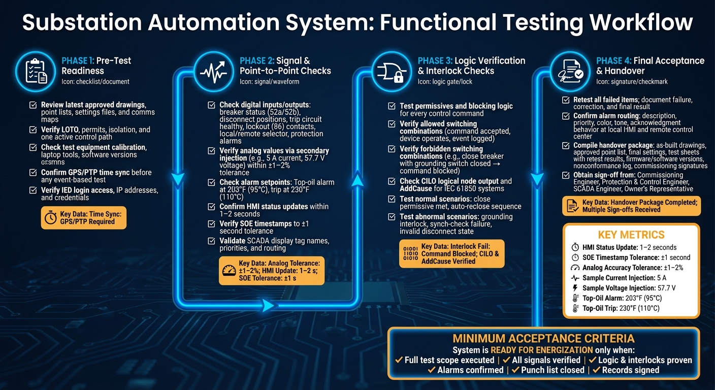
Substation Automation System Functional Testing Process
Electrical Grid Training Module 17B | Substation Automation System SAS Commissioning
sbb-itb-501186b
2. Pre-Test Readiness: Documents, Safety, and Test Setup
A readiness check before functional testing helps avoid rework, unsafe conditions, and bad test results. Running a clear pre-test sequence before any field checks start keeps the job moving and helps keep the team safe.
2.1 Review Final Documents and Point References
Use only the latest approved revision of every commissioning document. Testing against old drawings or settings files is a common reason for rework and delayed energization on substation projects.
Keep a document register at the site. A simple spreadsheet works well. It should list each document ID, title, current revision, date, and owner. The lead commissioning engineer should sign off on it before testing starts. Mark field changes on controlled prints, then send those updates through engineering so they can be added to the as-built drawings.
Cross-check the I/O list, SCADA point map, and field tags for every IED and RTU. Make sure names, addresses, units, and alarm priorities match before signal checks begin. Use the point reference index as the master map for signal checks. Those same point references continue into Section 3, so checking them now helps avoid reference mix-ups during signal verification.
Once the point map is confirmed, signal checks can begin without reference conflicts.
2.2 Verify Safety Clearances, Isolation, and Permits
Finish the written job safety plan, pre-job briefing, and work-permit review before any electrical testing starts.
Apply LOTO to all designated breakers, disconnects, and control power supplies, and mark the switching boundary on the one-line diagram. Keep radio or phone contact with the control center the whole time so test actions aren't mistaken for actual system events.
Set one active control mode for each test phase and turn off the other path. Disable remote control or enable test mode where the system allows it. This isolation step matters because it supports later interlock and logic testing by making sure only the intended control path is active during each check.
After safety steps and control authority are in place, move into device-by-device verification.
2.3 Check Test Equipment and Communications Access
Verify that all test equipment is calibrated, working, and compatible with site devices. Run a quick output check before taking anything into the field. Commissioning laptops should also be checked for software versions, security patches, drivers, and battery or charging status.
Confirm GPS or PTP time sync before any event-based test. If clocks don't line up, event logs and disturbance records become unreliable, and post-test analysis can fall apart.
Log into a sample of IEDs and gateways from engineering laptops. Confirm IP addresses, user credentials, and software version compatibility. Then verify login access to IEDs, gateways, the HMI, and SCADA point views. When access is verified and time is synced, the next alarm and event checks are much more dependable.
With documents, isolation, equipment, and access checked, move to point-to-point checks.
3. Signal and Point-to-Point Checks
With the drawings, isolation, and test gear in place, the next step is to check each signal path from the field device all the way to the HMI and SCADA. This is where you confirm the inputs are right before you get into logic and interlock checks.
3.1 Check Digital Inputs, Outputs, and Status Indications
Begin at the field device. For breaker status, check the 52a/52b contacts with a multimeter, then make sure the relay input changes state when the breaker is operated locally. If the contact logic is inverted, note it clearly in the relay settings.
Once the relay side looks right, check the HMI single-line diagram and make sure it shows the correct open/closed symbol based on the site display convention. Status changes should show up within 1–2 seconds on a local HMI, and the sequence-of-events (SOE) timestamps should line up with the relay event record to about ±1 second. Then work with the control center to confirm the signal appears the right way on the SCADA display under the correct substation, breaker, and feeder name.
Breaker status is only part of the job. The minimum set of binary points to check also includes:
- Disconnect and earthing switch positions
- Trip circuit healthy and trip coil monitor alarms
- Lockout (86 device) contacts and reset status
- Local/remote control selector state
- Protection alarms such as relay self-supervision, communication failure, and DC supply low
Stimulate each point at the device or terminal block so you verify the full chain, not just the relay output.
3.2 Verify Analog Values and Alarm Points
For analog signals, apply known test values with a secondary injection test set and confirm the reading stays accurate at every layer. For current and voltage, inject a value such as 5 A or 57.7 V and check that the CT/PT ratios in the relay settings match the equipment nameplate. Most utilities accept metering-grade readings within ±1–2% at the relay, with HMI and SCADA values matching aside from small rounding differences.
Alarm checks need a bit more care. Ramp through the setpoint - for example, a top-oil high alarm at 203°F (95°C) - and record the exact pickup and dropout values, along with any configured hysteresis. Then confirm the alarm shows up in the relay event list, triggers the right HMI banner and priority, and routes to SCADA with the correct tag name and priority category. Compare timestamps across the relay, HMI, and SCADA. A tolerance of ±1 second is commonly accepted for SOE records.
3.3 Use a Commissioning Results Table
Record each point, the test method, the expected value, and the result. The table below gives you a clean way to log the core point checks. If something fails on the first pass, add a comments column or a deficiency number so nothing gets lost.
| Signal/Point Name | Signal Type | Expected State/Value | Test Method | Displayed Location | Result |
|---|---|---|---|---|---|
| BRK 101 Open/Close Status | DI | Open when 52 open; Closed when 52 closed | Local manual breaker operation | Relay R1, HMI Feeder 101, SCADA BRK101 | Pass |
| BRK 101 Trip Circuit Healthy | DI | Healthy = ON; Alarm = OFF | Simulate trip coil open per utility procedure | Relay alarm list, HMI alarm banner, SCADA alarm queue | Pass |
| Lockout 86 Operated | DI | ON when lockout picked up | Controlled lockout operation via test switch | Relay R1, HMI bay overview, SCADA event log | Pass |
| Local/Remote Selector | DI | Local = remote commands blocked; Remote = commands allowed when permissives are satisfied | Toggle selector; attempt remote trip from HMI | Relay status, HMI control screen | Pass |
| Phase A Current (Ia) | AI | Matches injected value ±2% | Secondary injection at 5 A, 10 A | Relay metering, HMI analog display, SCADA tag | Pass |
| Bus Voltage (kV) | AI | Matches injected value ±2% | Secondary injection at 57.7 V (PT secondary) | Relay metering, HMI single-line, SCADA tag | Pass |
| Transformer Top-Oil Temp | AI | Alarm at 203°F (95°C); Trip at 230°F (110°C) | RTD calibrator at 40°C, 80°C, 110°C (104°F, 176°F, 230°F) | Relay, HMI alarm banner, SCADA alarm queue | Pass |
| Communication Failure Alarm | Alarm | Alarm present when communications are lost | Use relay test features or a controlled simulation, such as pulling the comm cable or switching to test mode | Relay, local HMI, SCADA control center | Pass |
Use these results as the baseline for permissive and interlock testing.
4. Logic Verification and Interlock Checks
Once the signal paths are confirmed, the next step is simple in theory but often where problems show up: prove the control logic works the way it should.
The system must accept commands only under the right conditions. It must block them when conditions are wrong. And in both cases, it should create the right alarm and event record.
4.1 Verify Permissives, Blocking Logic, and Control Paths
Start with the point references confirmed in Section 3 and test each control path one by one. Since the inputs and outputs are already checked, the job here is to confirm how the logic uses them.
List every command that can change breaker or feeder state, along with the conditions needed for that command to go through. Then apply the same approach to each scheme: trace the input, the logic, and the final output.
For each command:
- Force the required inputs into the proper state
- Issue the command
- Verify whether the command is accepted or blocked
- Check the event logging
- Record the command, the block reason, and the interlock state
Blocking functions need just as much attention as successful operations. Test auto-reclose blocks, transfer scheme blocks, and maintenance or grounding blocks by forcing the block condition active and then trying the related command. The system should reject the command and create the configured alarm or event record.
This part matters. If you test only successful commands, it's easy to miss commissioning defects that show up only when the logic is supposed to say no.
4.2 Check Breaker, Disconnect, and Feeder Interlocks
Test every forbidden condition that could allow an unsafe close or transfer. Build a matrix of allowed and forbidden switching states that includes breaker, disconnect, grounding switch, and energized condition.
Then work through each forbidden combination. For example, try to close a breaker while the grounding switch is closed. Confirm that the command is blocked both at the local panel and from the remote HMI.
For IEC 61850-based systems, check the CILO (Control Interlocking) logical node output for each blocked attempt. CILO and AddCause should show blocked or interlocked, not ready.
After that, run through each allowed combination and confirm that:
- The command is accepted
- The device operates
- The event log shows the operation with no interlock block flags
4.3 Test Normal and Abnormal Operating Scenarios
Use normal scenarios first to confirm the system works under valid conditions. A breaker close after all permissives are met, a feeder transfer with no blocked alarms, and an auto-reclose sequence that runs as expected are good baseline checks. Trace each test from the trigger all the way to the event record.
Abnormal scenarios show whether the system prevents unsafe actions. Simulate a broken breaker status input, force a synch-check failure, or create an invalid breaker/disconnect combination. Then confirm the command is blocked and that the operator gets a clear block indication.
For each case, record the setup, stimulus, expected result, actual result, and the alarm or event reference. That record supports final acceptance and gives the maintenance team a solid baseline to work from later.
Use the table to track the scenario details:
| Scenario Type | Example Test | Expected Outcome |
|---|---|---|
| Normal – Close permissive met | All permissives satisfied; issue close command from HMI | Breaker closes; HMI shows closed; event logged with no block flags |
| Normal – Auto-reclose sequence | Protection trip clears; reclose conditions met | Breaker recloses as expected; event log matches the operation |
| Abnormal – Grounding interlock | Grounding switch closed; attempt breaker close | Command blocked; CILO shows blocked; HMI alarm generated |
| Abnormal – Synch-check failure | Force synch-check relay to indicate out-of-sync | Close command rejected; alarm generated; no breaker movement |
| Abnormal – Invalid disconnect state | Disconnect open; attempt breaker close | Command refused; HMI shows blocked status; event log captures cause |
Log any failed permissive or interlock test for retest during final acceptance.
5. Final Acceptance, Retesting, and Handover
Once the signal, logic, and interlock checks pass, the focus shifts to closing defects and putting together the handover package.
5.1 Retest Deficiencies and Confirm Alarm Routing
Retest every failed item and document three things: the failure, the correction, and the final result. Use the same point references and alarm tags already checked in Sections 3 and 4 so the records stay aligned.
Each alarm point needs an end-to-end retest. Start at the local HMI. Confirm that the alarm shows the correct description, priority, color, tone, and acknowledgment behavior. Then check the remote control center and make sure the same alarm arrives with the matching description, priority, and device association. Local and remote timestamps should match the SOE record. The alarm should also follow the expected sequence: flashing with audible indication when it occurs, steady after acknowledgment, and cleared only after the condition is gone and the operator resets it.
During retesting, use relay or IED test mode. That way, published GOOSE or sampled value data is treated as test data and won't affect in-service devices on the same network.
5.2 Complete As-Built Records and Test Sign-Off
The handover package needs to match what was actually installed in the field. After retesting is done, compile the final record set. Any change made during commissioning must be captured, including updated wiring diagrams, revised IED settings files with version control, current IEC 61850 SCL and GOOSE configuration files, and the final alarm matrix.
A complete package usually includes:
- as-built drawings and files
- the approved point list
- final approved settings
- test sheets with retest results
- firmware and software versions for every device
- the nonconformance log with closure records
- all commissioning signatures
Get sign-off from the commissioning engineer, protection and control engineer, SCADA engineer, and the owner's representative or operations manager.
5.3 Conclusion: Minimum Criteria for Functional Acceptance
A substation automation system is ready for energization only when all of these items are complete:
- Test scope fully executed: protection, control, interlocks, measurements, communications, and HMI/SCADA functions all tested.
- Signals verified: every digital input, output, and analog value confirmed between the field, IEDs, and operator interfaces.
- Logic and interlocks proven: permissives, blocking logic, and interlock schemes tested in both normal and abnormal scenarios.
- Alarms confirmed: routing, priority, timestamps, and acknowledgment behavior validated at the local HMI and remote control center.
- Punch list closed: all deficiencies affecting safety, protection reliability, or monitoring corrected and retested.
- Records signed: as-built drawings and files, final approved settings, and test sheets approved by all required parties before energization.
Any open item tied to safety or protection must be fixed before energization. Minor labeling or cosmetic items can be logged for controlled closeout.
FAQs
What should be tested before energization?
Before energization, check the basics first: correct wiring and terminal connections, acceptable insulation resistance, proper grounding and bonding, and stable DC and auxiliary power.
Then work through the control and protection side. Confirm end-to-end I/O and binary signal mapping, relay settings and protection logic, communication links, interlocks/permissives, and all alarms/indications/annunciation at the panel, HMI, SCADA, and event logs. Finish with a final check of labeling and documentation.
How do you verify interlocks and permissives?
Verify that the control logic blocks unsafe switching before energization. Do this by operating field equipment or by using simulated inputs to create the required states.
Check the response at the field device, local panel, and SCADA. For logic-based interlocks, test each input combination against the approved test matrix, confirm auxiliary contact polarity and wiring, and remove all temporary bypasses or overrides before energization clearance.
What happens if a point or alarm fails testing?
If a point or alarm fails testing, add it to the commissioning punch list. Record the point ID, the defect description, the suspected cause, the planned corrective action, and the scheduled re-test date.
The item stays open until it passes re-testing. Safety-critical alarms must pass with no open items before system energization.





