




How to Ensure EMC Compliance in Power Systems
Electromagnetic compatibility (EMC) ensures that electrical systems work without causing or being affected by interference. This is critical for power systems, which often generate or suffer from electromagnetic interference (EMI). Failing EMC tests can lead to costly redesigns, safety risks, and regulatory penalties. Here's a quick breakdown of what you need to know:
- Why It Matters: Non-compliance can cause equipment failures, safety hazards, and project delays. Testing costs can reach up to $20,000 per submission.
- Key Standards: Global standards like IEC 61000 and CISPR set emission and immunity requirements. U.S. regulations include FCC Part 15 for emissions and IEEE 1159 for power quality.
-
Design Tips:
- Use EMI filters (e.g., π-filters) to block noise.
- Design PCBs with minimal loop areas and continuous ground planes.
- Shield cables and components to reduce emissions.
-
Testing:
- Start with pre-compliance testing to catch issues early.
- Use certified labs for final testing to meet legal requirements.
- Troubleshooting: Identify interference sources and apply fixes like better shielding, optimized layouts, or frequency dithering.
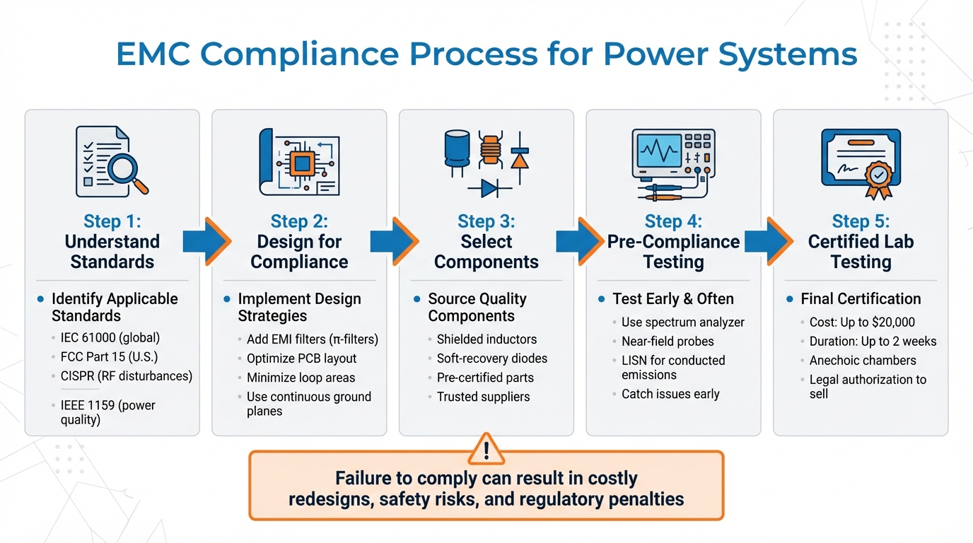
5-Step EMC Compliance Process for Power Systems
Understand EMC Standards and Regulations
Key EMC Standards Overview
The IEC 61000 series serves as the global foundation for electromagnetic compatibility (EMC), setting emission limits for power supply systems and dividing equipment into four categories: Components, Systems, Apparatus, and Installations. These categories guide the development of design strategies to ensure compliance with EMC requirements.
The CISPR standards focus on managing radio-frequency disturbances. For example, CISPR 11 addresses industrial, scientific, and medical equipment, CISPR 14-1 applies to household appliances, and CISPR 22 governs information technology equipment. It's important to note the difference between general EMC standards, which cover testing methods, and product-specific standards, which target particular equipment like electricity meters or printed circuit boards.
When it comes to current levels, different standards apply:
- For equipment drawing ≤16 A per phase, IEC 61000-3-2 and IEC 61000-3-3 are relevant.
- Devices using 16–75 A fall under IEC 61000-3-12.
- Systems with higher currents must follow IEC/TS 61000-3-4 and IEC/TS 61000-3-5.
- Medium to extra-high voltage installations are covered by IEC/TR 61000-3-6 and IEC/TR 61000-3-7.
EMC Regulations in the United States
In the United States, FCC Part 15 (47 CFR 15) sets the rules for EMC compliance, primarily focusing on emissions to protect radio services. While power systems are generally classified as "incidental radiators", they face stricter limits if they use Broadband over Power Line (BPL) or Power Line Communication (PLC) technologies.
U.S. regulations prioritize safeguarding radio navigation and safety services, defining harmful interference as emissions that jeopardize these services or severely disrupt radiocommunications. For power quality monitoring, IEEE 1159 provides the necessary framework, while international systems often rely on EN 50160 for voltage characteristics. Additionally, equipment intended for substations or power stations must comply with IEC 61000-6-5, which specifies the higher immunity levels required for the challenging electromagnetic conditions in utility environments. These regulations shape both pre-compliance and full-compliance testing processes, ensuring equipment meets stringent performance criteria.
sbb-itb-501186b
How to Pass Conducted EMC and Immunity. 5 Tricks
Design Strategies for EMC Compliance
Meeting EMC standards requires thoughtful design strategies aimed at reducing emissions and ensuring smooth operation.
Add EMI Filtering Solutions
EMI filters are your first line of defense against unwanted noise, especially at power inputs. A common choice is the π‑filter, which combines two capacitors in parallel with a series inductor to block conducted EMI before it reaches sensitive circuitry.
For effective filtering, the output impedance of the filter should stay at least 10 dB lower - about one-third - of the converter's input impedance up to the crossover frequency. For instance, if a converter has an input impedance of 7.6 Ω, the filter's output impedance should remain below approximately 2.5 Ω.
Analog Devices showcased this principle in June 2018 with its MAXM17575 Himalaya SiP power module (4.5V to 60V input, 1.5A output). By incorporating a π‑filter with a 10 μH inductor (Pulse Electronics model PA4332.103NLT) and 1 μF and 10 μF capacitors, the design achieved CISPR 22 Class B compliance. This setup ensured the filter's output impedance stayed within the required limits.
When choosing filters, consider the application:
- Use π‑filters for general noise reduction.
- Opt for T filters for low-impedance, high-current applications.
- Select L filters for load-switched DC lines and high-power scenarios.
PCB and Cable Design Best Practices
Good PCB and cable design can significantly reduce radiated emissions. Start by minimizing loop areas, as smaller loops generate less radiation. A multi-layer PCB with continuous ground planes offers a low-impedance return path, which can cut EMI emissions by 10–20 dB when placed near power components.
Faraday shielding provides another layer of protection. High di/dt loops can be enclosed within inner PCB layers, surrounded by via-stitched ground planes on the top and bottom. This creates an electromagnetic cage that effectively contains emissions.
For cable management, twisted-pair cables are a smart choice since they help cancel out electromagnetic fields. Keep cable lengths short to prevent them from acting as antennas, and always separate signal cables from power cables to avoid crosstalk. Shorter PCB traces are also beneficial, as typical traces introduce about 20 nH of inductance per inch - longer traces mean more parasitic inductance and higher EMI.
Strategic component placement is equally critical. Noisy elements like oscillators and switching power supplies should be positioned away from sensitive analog components. Decoupling capacitors should be placed as close as possible to IC power pins to provide a direct path for high-frequency noise to ground. For transformers, consider center-gapped designs and include a Faraday shield (thin copper foil between primary and secondary windings) to direct noise currents to ground.
These practices lay the groundwork for selecting the right components to further enhance EMC performance.
Source Quality Components
Once your design strategies are in place, choosing high-quality components is the next step to ensure EMC compliance. Shielded inductors, for example, keep magnetic fields contained within the component, unlike unshielded versions, which can radiate noise. Texas Instruments Principal Engineer Sanjaya Maniktala has likened unshielded inductors to "EMI cannons".
Other component choices can also make a big difference. Soft-recovery diodes or RC snubbers across diodes help reduce high-frequency ringing and noise spikes. For additional reliability, source components from trusted suppliers. Electrical Trader (https://electricaltrader.com) offers a variety of new and used electrical parts, such as breakers, transformers, and power distribution equipment, that are essential for maintaining system-level EMC compliance. Pre-certified breakers and transformers from reputable vendors reduce the likelihood of introducing unexpected EMI sources into your system.
Component-level adjustments can further suppress noise without sacrificing efficiency. For instance, adding a nickel-zinc ferrite bead in series with output diodes can significantly cut high-frequency noise and ripple. Similarly, for switching regulators, slowing down FET switching speeds by adding a resistor (typically 10 Ω to 100 Ω) in series with the gate can effectively reduce high-frequency harmonics while maintaining performance.
Once these measures are implemented, rigorous pre-compliance testing will help validate your design's EMC performance.
Test and Validate EMC Compliance
After carefully designing your system and selecting the right components, the next critical step is rigorous testing to ensure your system meets Electromagnetic Compatibility (EMC) standards. This phase is all about confirming that your design effectively reduces interference. Many projects fail their first certified lab test due to unexpected interactions between circuit elements. To avoid costly redesigns, it's smart to use a two-phase testing approach: start with pre-compliance testing, then move on to formal certification.
Pre-Compliance Testing
Pre-compliance testing helps identify and fix EMC issues early in the design process, saving time and money before heading to certified labs. Begin by determining the standards applicable to your product and market. For example:
- CISPR standards apply to international markets.
- FCC Part 15 governs U.S. consumer products.
- EN standards cover European industrial equipment.
Your product type - whether it's Industrial, Medical, Automotive, or IT-related - will dictate the specific standards you need to follow.
The testing environment is just as important. Choose a location with minimal ambient electromagnetic noise to avoid interference from nearby sources like cell towers or radio broadcasts. For radiated emissions testing, set up a calibrated EMI antenna 3–10 feet (1–3 meters) from your device and connect it to a spectrum analyzer. Conducted emissions testing (covering the 150 kHz to 30 MHz range) requires a Line Impedance Stabilization Network (LISN) to isolate power mains and accurately measure cable noise.
To pinpoint problem areas, use near-field probes to locate components or PCB traces emitting excessive radiation. Harmonic markers on your spectrum analyzer can help identify emissions tied to known clock frequencies. Always compare powered-on and powered-off measurements to distinguish internal noise from external interference.
Once pre-compliance testing resolves any issues, you're ready to move to full-scale testing in certified labs.
Full-Compliance Testing in Certified Labs
After successful pre-compliance testing, it's time for formal certification in a certified lab. This step can cost up to $20,000 per submission and may take up to two weeks to complete. While expensive, this process is essential for securing legal authorization to sell your product, as federal regulations require electronic devices to meet EMC standards.
Certified labs use specialized facilities like anechoic chambers - shielded rooms that absorb electromagnetic reflections - or Open-Air Test Sites (OATS). These environments are designed for detailed testing of both emissions (energy leaving your device) and immunity (your device's ability to operate despite external interference). For power systems, immunity testing assesses performance based on four classifications:
- Class A: No loss of function.
- Class B: Temporary loss of function that recovers automatically.
- Class C: Loss of function requiring operator intervention.
- Class D: Permanent damage.
Before scheduling lab tests, ensure your device is production-ready and connected to all necessary peripherals. Choose an FCC-accredited or otherwise certified lab to ensure your results are legally recognized. The controlled lab environment, with its precise regulatory procedures, calibrated equipment, and specialized software, guarantees your power system meets all requirements before it hits the market. This final step ensures your product is ready for reliable deployment.
Troubleshoot and Fix EMC Problems
Even with thorough design and testing, EMC failures can still happen. When they do, a structured approach is essential to pinpoint the root cause and apply the right fixes. Most EMC issues fall into familiar categories, and there are established solutions for each.
Common Causes of EMC Failures
Human-made interference is a frequent cause of EMC problems. This happens when devices or large electrical systems, like power lines, generate signals that overlap at the same frequency.
Modern power converters are particularly troublesome because they operate at high switching frequencies and use fast-switching components. These converters are major contributors to electromagnetic disturbances.
Inherent EMI stems from the device itself. Internal electrical systems can interact in ways that create interference, even when shielding is in place. At higher frequencies, parasitic effects in components can reduce the effectiveness of EMI filters. Additionally, power supplies that lack power factor correction (PFC) can draw non-sinusoidal current, leading to harmonic currents that may overheat neutral wires in power systems.
Other common causes include inadequate power supply filters, high ground impedance, poor signal return paths, component parasitics, insufficient cable shielding, and discontinuous return paths. Natural sources, like rainstorms, solar radiation, and even celestial bodies such as Jupiter, can also emit EMI. However, these natural sources are generally less disruptive than human-made interference.
How to Fix EMC Issues
Once the sources of interference are identified, the next step is to address them with targeted solutions. Start by identifying both the energy source (e.g., switching power supplies) and the "antenna" radiating that energy (e.g., cables or PCB traces). Use field probes and test meters to locate emission sources. Since cables are often the primary radiators of RF energy, moving current probes along their length can help identify areas with the highest harmonic currents for precise filtering.
Frequency dithering is one effective technique. It spreads energy over a broader band, reducing peak emissions by as much as 10 dB or more. For instance, in tests with a buck converter using the LM5088-1 controller, enabling a ±5% dithering function resulted in a 20 dB reduction in peak emissions. As engineers Bob Bell and Ajay Hari from National Semiconductor put it:
"There is no substitute for good layout, design and filtering practices... However, not every power converter is designed under ideal conditions".
To minimize high-frequency emissions, consider adding snubbers across Schottky diodes, using 10–100 Ω gate resistors to control FET turn-on, and employing soft-recovery diodes to reduce noise . When layout issues are a factor, reduce the size of high-frequency current loops and avoid wide traces with swinging voltages, as these can function as E-field antennas.
Shielding is another practical solution. Techniques like vacuum metalizing or applying conductive coatings to electronic housings and PCB shields can mitigate both human-made and internal EMI without requiring a complete circuit redesign. Adding EMI filters to input power lines is also a reliable method for reducing conducted emissions. Transformer-related issues can be addressed by burying the "Drain" end of the primary winding as the first layer to shield swinging voltage fields and using center-gapped cores to minimize fringing fields from outer limb gaps.
Effective troubleshooting involves relative measurements to isolate sources, while compliance testing requires absolute, calibrated measurements in controlled settings. Start with near-field probes, then measure cable radiation with current probes, and finally verify results with a 1-meter antenna test. This step-by-step approach ensures you tackle the real problem without wasting time or resources on ineffective fixes. These strategies, combined with early design and pre-compliance testing, can help achieve full EMC compliance.
Conclusion
Summary of EMC Compliance Steps
Getting EMC compliance for power systems requires careful planning right from the design phase all the way to final certification. Start by determining the relevant standards for your application - whether it's FCC Part 15 for general electronics, CISPR 22/32 for multimedia equipment, or EN61204-3 for power supplies. From there, design with electromagnetic field control in mind. Techniques like placing ground planes close to signal and power paths can help reduce stored energy. Use proper filtering methods, such as bypass capacitors and inductors, to suppress both differential and common mode noise. Also, refine your PCB layout by minimizing antenna loop areas and avoiding sharp bends.
Pre-compliance testing is a valuable step to catch potential problems early. Tools like spectrum analyzers and near-field probes let you identify issues before committing to costly lab certifications. If problems arise, take a structured troubleshooting approach: identify the energy source and the radiating "antenna", then apply targeted solutions such as better shielding or additional filtering. The goal is to manage electromagnetic fields effectively, ensuring every accelerating charge has a proper return path to cancel out unwanted fields. Following this methodical approach ensures that every design decision supports successful EMC compliance.
Use Trusted Platforms for Compliance
In addition to solid design and testing practices, choosing high-quality components is a key factor in avoiding EMC failures. The quality of your components directly affects your compliance efforts. Sourcing reliable parts - like low-ESR ceramic capacitors, coupled choke inductors, and ferrite beads - can prevent costly redesigns.
Platforms such as Electrical Trader offer access to a wide range of power distribution equipment, including both new and used components from reputable manufacturers. These include breakers, transformers, and specialized EMI mitigation parts. Purchasing from trusted marketplaces ensures you receive components with proper technical documentation and compliance certifications, which are critical for creating an accurate EMC test plan. By prioritizing quality components from the outset, you increase your chances of passing certification on the first try, keeping your project on track and within budget.
FAQs
What happens if a power system doesn’t meet EMC compliance standards?
Failing to meet EMC compliance standards can have serious consequences. Your equipment might malfunction, completely shut down, or interfere with nearby devices, causing disruptions. These issues can lead to operational downtime, safety hazards, and expensive repair bills.
On top of that, non-compliance can bring legal penalties, block access to certain markets, and tarnish your reputation. Meeting compliance standards isn’t just a box to check - it’s a critical step to ensure your power systems are reliable, safe, and ready for the market.
What is pre-compliance testing, and how does it help with EMC compliance?
Pre-compliance testing serves as an early checkpoint to ensure your power system design aligns with electromagnetic compatibility (EMC) standards. Tackling potential issues at this stage can help you sidestep expensive delays and redesigns later in the certification process.
To begin, use portable tools like a spectrum analyzer to measure emissions from your prototype. Compare these measurements to relevant U.S. standards, such as FCC Class A or B, to identify problem areas. Once you’ve pinpointed emission sources - like switching circuits or improperly shielded cables - you can implement targeted fixes. Common adjustments include adding filters or enhancing shielding. After making these changes, re-test your design to verify improvements and document your findings. This documentation will help simplify the final certification process.
Incorporating pre-compliance testing into your workflow not only saves time and money but also boosts your confidence in achieving full EMC certification.
How can I reduce electromagnetic interference (EMI) in power systems?
To reduce electromagnetic interference (EMI) in power systems, it's all about smart design choices. Start by establishing a solid grounding system. Connect all low-impedance ground points to a single star ground, and ensure ground-return paths are as short as possible. For signal lines, opt for twisted-pair or shielded cables - this helps cancel out magnetic fields and block unwanted emissions. When working on PCB layouts, keep high-frequency components grouped closely, minimize loop areas, and separate noisy traces from sensitive ones to avoid interference.
Adding EMI filters can also make a big difference. Use common-mode chokes and capacitors at the power entry to cut down on conducted emissions. For transformers, include shielding between windings to prevent them from acting like antennas. Enclosing noisy components in metal cases with proper grounding is another effective way to contain emissions. Finally, choose components that meet established EMI standards, sourcing them from reliable suppliers like Electrical Trader. This ensures compliance with U.S. regulations, including FCC Part 15.





