Common Power Distribution Faults and Fixes
Power distribution systems are critical for delivering electricity safely and reliably. However, faults like short circuits, ground faults, overloads, and voltage drops can disrupt operations and lead to costly downtime. These issues often arise from aging equipment, poor maintenance, or incorrect loading. Here's a quick summary of key takeaways:
- Fault Symptoms: Short circuits cause instant trips; overloads lead to heat and burnt smells; ground faults make equipment frames "live."
- Diagnosis: Use tools like multimeters, insulation testers, and thermal cameras to identify issues. Always follow safety protocols like Lockout/Tagout (LOTO).
-
Common Faults:
- Short Circuits: Fix by isolating the circuit and replacing damaged components.
- Ground Faults: Test insulation resistance and repair faulty cables or splices.
- Overloads: Check for excessive current draw and address motor or load issues.
- Voltage Drops: Measure load voltage and upgrade wiring if needed.
- Prevention: Regular maintenance, thermal imaging, and upgrading outdated equipment reduce risks.
- Quick Repairs: Platforms like Electrical Trader can help source replacement parts quickly, minimizing downtime.
Recognizing and Diagnosing Fault Symptoms
Common Fault Symptoms
Different types of faults show up in distinct ways. For example, short circuits often cause instant trips accompanied by loud bangs or flashes. On the other hand, overloads tend to build up over time, with warning signs like excessive heat, burnt smells, or discolored wiring. Ground faults can be trickier to spot; if an equipment frame feels "live" to the touch, it’s a serious shock hazard that needs immediate attention. If a motor or device stops working altogether, it’s likely due to an open circuit caused by something like a blown fuse, a broken wire, or a loose terminal.
Intermittent issues deserve special attention too. Flickering lights, equipment that randomly resets, or breakers that trip only under heavy loads often point to loose connections that expand and contract with temperature changes. Once you notice these signs, it’s time to start a systematic diagnostic process to find the root cause.
First Steps in Diagnosing Faults
Before diving into any hands-on troubleshooting, always follow Lockout/Tagout (LOTO) procedures. This means notifying all personnel, shutting down and isolating the equipment, applying locks and tags, and double-checking that the system has no residual energy.
"Rely on test instruments and a systematic process." - Dovient Learning
Start with a thorough visual inspection. Look for obvious signs like burn marks, melted insulation, moisture, or corrosion. This step alone can uncover 30% to 40% of faults. Next, use tools like a digital multimeter (DMM), clamp meter, or insulation resistance tester to gather more data. Tug on wire connections - loose terminations are a common culprit. Always test your meter on a known live source before and after use to ensure accuracy.
Source vs. Load-Side Faults: How to Tell the Difference
A quick voltage check at the main disconnect can help you figure out whether the fault is upstream (source-side) or downstream (load-side). If there’s no voltage or very low voltage at the disconnect, the issue is likely upstream - this could mean a utility outage, a blown service fuse, or a failed transformer. But if the voltage at the disconnect is normal and missing at the motor or device terminals, the problem is downstream, possibly in the wiring, contactors, or terminals.
Voltage measurements at key points can narrow things down further:
| Test Point | Voltage Present? | Likely Fault Location |
|---|---|---|
| Main disconnect | No | Source-side (utility, service entrance, feeder breaker) |
| Main disconnect | Yes | Load-side (feeders, branch circuits, terminals) |
| Load terminals | No (source OK) | Wiring, contactors, or subpanel downstream |
From here, trace the circuit step by step - from the source to the feeder, then to the branch circuit, and finally to the load. Test continuity through switches, relays, and subpanels along the way. In a well-designed system, the protective device closest to the fault should trip while upstream devices stay active. For instance, if only a branch breaker trips while the main breaker holds, it’s a clear sign that the fault is isolated to that branch.
sbb-itb-501186b
Electrical faults explained types, causes, calculations, and protection
Common Power Distribution Faults and How to Fix Them
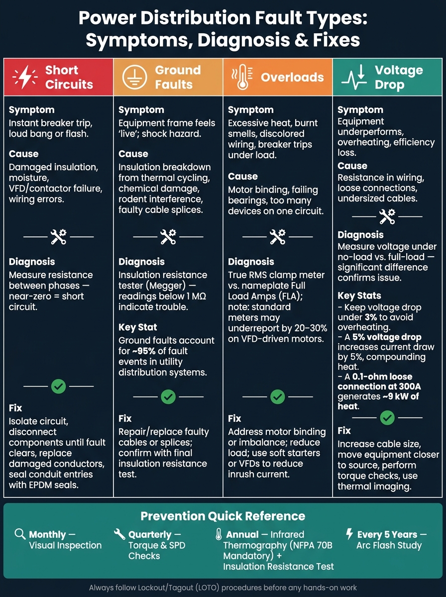
Power Distribution Fault Types: Symptoms, Diagnosis & Fixes
Short Circuits and Ground Faults
When dealing with power distribution issues, it’s essential to figure out if the problem lies on the source side or the load side. Two of the most frequent and destructive faults you’ll encounter are short circuits and ground faults.
A short circuit happens when a low-impedance path unintentionally forms between conductors of different potentials, like phase-to-phase or phase-to-neutral. This bypasses the load, leading to a sudden and extreme current spike. Causes often include damaged insulation (from heat or physical stress), moisture entering enclosures, failures in components like VFDs or contactors, or wiring errors during installation. To diagnose, measure resistance between phases; near-zero resistance points to a short circuit.
A ground fault, on the other hand, occurs when an energized conductor makes unintended contact with a grounded surface, such as a conduit or equipment frame. These faults are incredibly common, accounting for about 95% of fault events in utility distribution systems. Typical culprits include insulation breakdown from thermal cycling, chemical damage, rodent interference, or faulty cable splices. Use an insulation resistance tester (often called a Megger) to check for ground faults - readings below 1 megaohm usually indicate trouble. In grounded systems, these faults can produce enormous currents, making ground fault protection equipment (GFPE) mandatory for certain high-capacity services.
To repair either type of fault, isolate the affected circuit by systematically disconnecting components until the fault disappears. Replace damaged conductors, seal conduit entries with EPDM seals or fiberglass caps to prevent moisture, and confirm the fix with a final insulation resistance test before restoring power.
Once these faults are resolved, you can move on to addressing load-related issues like overloads and voltage drop.
Overloads and Voltage Drop
Overloads and voltage drop are distinct problems but equally critical to address. An overload occurs when a load draws more current than the circuit is designed to handle. This can happen due to issues like mechanical binding in a motor, a failing bearing, or simply overloading a circuit with too many devices. To diagnose, use a True RMS clamp meter to measure current on each phase and compare it to the equipment's nameplate full load amps (FLA). Be aware that standard meters may underreport by 20–30% on motors driven by VFDs.
Voltage drop arises when resistance in the wiring causes a drop in voltage as it travels from the source to the load. To identify it, measure voltage under both no-load and full-load conditions - a significant difference confirms the issue. Keep voltage drop under 3% to avoid overheating and efficiency losses. A 5% voltage drop can increase current draw by the same percentage, compounding heating problems.
Loose connections, like a 0.1-ohm resistance at 300 A, can generate about 9 kW of heat, potentially leading to terminal damage or fire. Regular thermal imaging surveys and torque checks can help catch these issues early. In facilities with many motors, using soft starters or VFDs can reduce inrush current during startup, cutting down on nuisance trips and mechanical wear.
Here’s a quick reference table for common issues and solutions:
| Issue | How to Identify | Fix |
|---|---|---|
| Overload | True RMS clamp meter vs. nameplate FLA | Check for motor binding, imbalance, or excessive load |
| Voltage Drop | Measure no-load vs. full-load voltage | Increase cable size or move equipment closer to the source |
| Loose Connections | Thermal imaging or terminal discoloration | Perform torque checks and replace damaged terminals |
| Inrush Current | Clamp meter during motor startup | Use soft starters or VFDs; stagger motor starts |
Tackling these issues promptly will help maintain system performance and prevent further complications.
Grounding and Bonding Problems
Proper grounding and bonding are vital for a safe and reliable power distribution system. While grounding provides a stable connection to the earth to stabilize voltage, bonding ensures metallic parts are electrically connected to create a low-impedance path for fault currents.
One critical rule: there should only be a single neutral-to-ground bond at the service entrance. In subpanels, the neutral and ground bars must remain separate. If multiple bonds exist, objectionable currents can flow on metal enclosures, increasing the risk of shock or fire. As Mike Holt explains:
"The service neutral conductor provides the effective ground-fault current path to the source to remove dangerous voltage from a ground fault by opening the circuit overcurrent protective device (OCPD)."
Corroded terminals or loose fittings can also create high-impedance ground paths. If ground impedance is too high, overcurrent devices may fail to trip during a fault, leaving equipment frames energized. For example, a ground impedance of 1 ohm at a 100A fault creates a hazardous 100 volts at the fault site. Use a low-resistance ohmmeter to verify grounding integrity; the resistance should be 0.25 ohms or less. Standard multimeters won’t provide the precision needed.
The NEC emphasizes:
"The earth shall not be used as the sole equipment grounding conductor or fault current path." - National Electrical Code (NEC) Section 250-2(d)
Finally, ensure all ground electrodes - whether they’re water pipes, structural steel, or ground rods - are bonded into a single system. A single ground rod should have a resistance of 25 ohms or less; if not, install a second rod at least 6 feet away.
How to Prevent Power Distribution Faults
Routine Maintenance and Testing
Stopping faults before they happen saves money and headaches. A well-planned maintenance schedule is key. This should include monthly visual inspections, quarterly torque and grounding checks, annual diagnostic surveys, and a comprehensive arc flash study every five years.
Thermal imaging is one of the most effective diagnostic tools available. As of 2023, the NFPA 70B standard mandates annual infrared thermography inspections for all electrical equipment. This change elevates what was once a recommended practice into a compliance requirement. Johnson, a Maintenance Expert at OxMaint, highlights the importance of this shift:
"The 2023 NFPA 70B standard has now made annual infrared thermography inspections of all electrical equipment mandatory, shifting electrical maintenance from a recommended practice to an enforceable compliance obligation." – Johnson, Maintenance Expert, OxMaint
When conducting thermal scans, pay close attention to the delta-T, or the temperature difference between similar components. If the delta-T falls between 25°C and 40°C (77°F–104°F), corrective action should be taken within 30 days. A delta-T exceeding 40°C (above 104°F), however, calls for an immediate shutdown. Other routine tests, like annual insulation resistance checks and circuit breaker trip tests, are equally important. After all, a breaker that fails to trip can compromise critical system protection.
| Maintenance Task | Frequency | Key Tool/Requirement |
|---|---|---|
| Visual Inspection | Monthly | Qualified Technician / LOTO |
| Torque Verification | Quarterly | Calibrated Torque Wrench |
| Infrared Thermography (IR) | Annual | Thermal Camera (NFPA 70B Mandatory) |
| Insulation Resistance Test | Annual | 500V or 1,000V Megohmmeter |
| Circuit Breaker Trip Testing | Annual | Calibrated Breaker Test Set |
| Arc Flash Study Update | Every 5 Years | Licensed Electrical Engineer |
In addition to regular maintenance, upgrading outdated equipment can significantly improve system reliability.
Upgrading Outdated Equipment
Older equipment often struggles to handle today’s energy demands. Devices like variable frequency drives (VFDs), high-inrush motors, and modern solar or battery systems can overwhelm legacy switchgear and breakers, which were not designed for such loads.
Modernizing with electronic trip units and advanced protection relays ensures selective coordination. This means that only the device closest to a fault isolates the issue, preventing unnecessary disruptions across the facility. Other upgrades - like arc-resistant switchgear, phase monitoring relays, and smart breakers with real-time monitoring - add extra layers of safety while helping identify potential problems before they worsen.
Compliance with updated codes is another reason to upgrade. For example, the 2023 National Electrical Code (NEC) expanded GFCI protection to include outdoor outlets, garages, and certain basement areas. If your system was installed under older code requirements, you might need targeted updates to meet current standards. As Trystar explains:
"Investing in advanced, strategically-engineered power distribution systems is essential for industrial facilities to achieve reliable operations, safeguard personnel and assets, and remain adaptable in an increasingly complex and demanding environment."
Upgrades like these not only improve reliability but also help you stay compliant with the latest regulations.
Protecting Systems from External Threats
Once your equipment is up to date, it’s important to shield it from external risks. Environmental and operational hazards - like moisture, wildlife, and power surges - can cause unexpected faults.
For instance, rodent infestations can lead to arc flashes. To prevent this, ensure panel doors are securely closed and unused knockouts are properly sealed. Surge protection is another critical step. Install Surge Protective Devices (SPDs) at service entrances and on pole-mounted equipment exposed to lightning. Check SPD status indicators quarterly - if an SPD fails, your system could be left vulnerable.
Proper ventilation in electrical rooms is equally important. Excessive heat can speed up insulation aging and increase the risk of faults. By addressing these external threats, you can further reduce the chances of unexpected failures.
Using Electrical Trader for Repairs and Upgrades
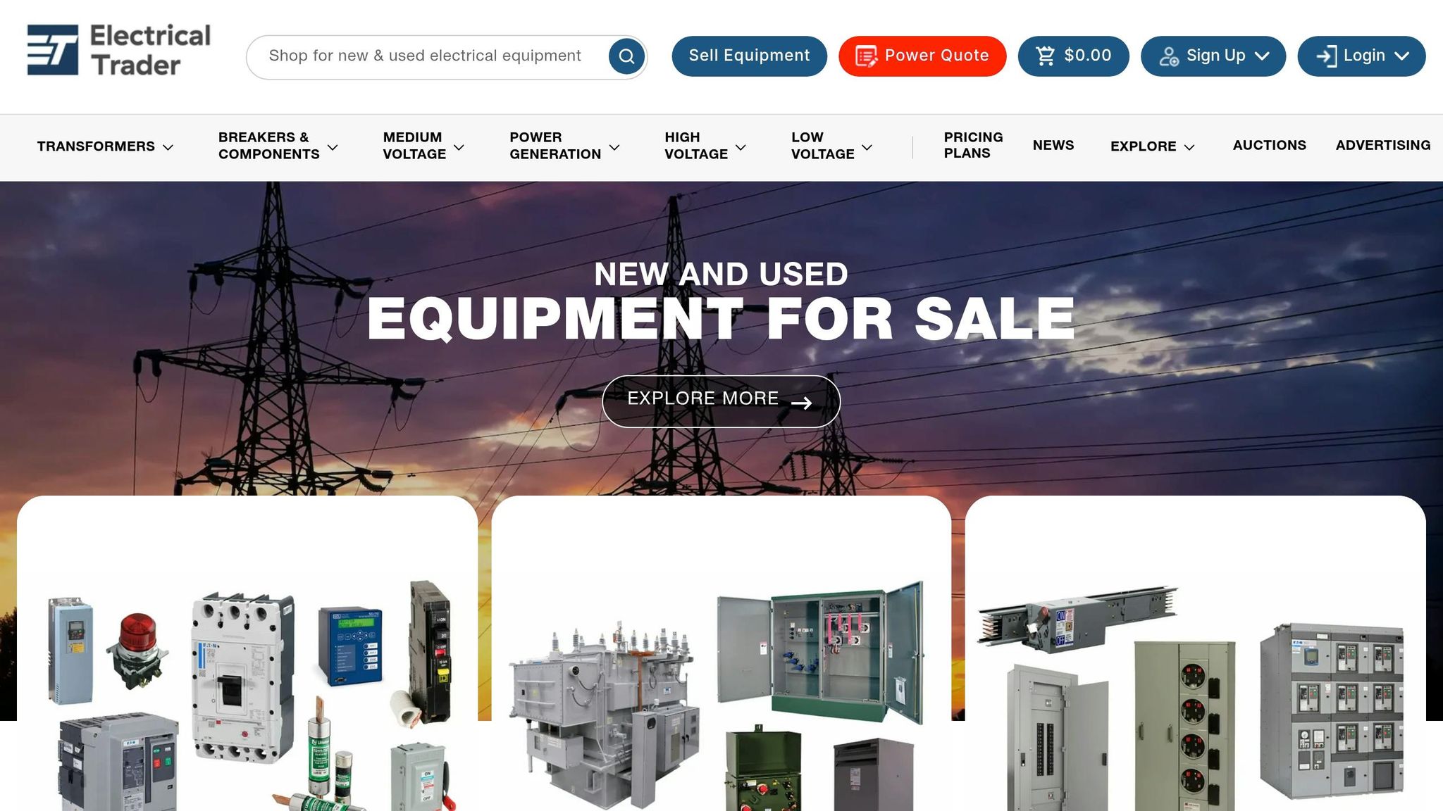
When dealing with power distribution faults, sourcing the right equipment quickly is vital. Electrical Trader simplifies this process by offering an online marketplace that connects buyers with new, surplus, and used power distribution equipment from various sellers. This eliminates the need for time-consuming phone calls and allows users to find the exact components they need more efficiently.
Finding Replacement Components
If a breaker fails or a transformer needs replacing, every moment counts. Traditional supply channels for high-voltage equipment often involve lead times of 18–36 months. However, surplus and refurbished inventory can be delivered in weeks, making a significant difference in downtime.
Electrical Trader provides a wide selection of replacement parts tailored to common power distribution issues. These include molded-case and insulated-case circuit breakers, fuses, protective relays, switchgear sections, and both dry-type and oil-filled transformers. For instance, the Square D PowerPact Circuit Breaker (200A) is listed at approximately $390, while Eaton Bussmann KTU-1000 Class L Fuses are available for around $585.
To ensure compatibility, use nameplate data - such as manufacturer, catalog number, voltage, frame size, trip rating, interrupting capacity, and mounting style - as search filters. For used or reconditioned items, always request test reports and maintenance records, particularly for critical devices like main breakers and relays, to verify their reliability.
Once replacement components are secured, you can explore equipment options for broader system improvements.
Sourcing Equipment for System Upgrades
Electrical Trader is not just for emergency repairs; it’s also a resource for system upgrades. The platform features panelboards, switchboards, motor control centers (MCCs), and larger-kVA transformers designed for upgrade projects. It also lists specialized equipment like harmonic mitigating panels for facilities with sensitive electronic loads, as well as surge protective devices (SPDs), line reactors, and transfer switches.
"Procurement of high-voltage transmission equipment through traditional supply channels involves long lead times - often 18 to 36 months for new transformers and breakers. Surplus and refurbished equipment from our inventory ships in weeks, not years, at a fraction of new cost." – Electrical Trader
For contractors, reconditioned equipment can offer significant cost savings. Used distribution panels are typically priced at 40%–70% of the cost of new ones, while certified reconditioned protection relays are generally 35%–65% of new pricing. Larger projects can benefit from used substation equipment, which is often available at 30%–60% of the cost of new units. These savings allow more budget flexibility for labor, testing, and commissioning.
Faster, Simpler Procurement
Electrical Trader consolidates options from multiple sellers into a single, easy-to-navigate platform. Users can filter listings by voltage, ampacity, brand, and condition (new, surplus, or reconditioned) while comparing prices in U.S. dollars. This is particularly useful for sourcing obsolete or discontinued components for legacy panels that are no longer in production.
"Whether you're upgrading your facility, sourcing replacement parts, or selling surplus inventory, Electrical Trader makes it simple, fast, and secure." – Electrical Trader
For critical components like main breakers and relays, prioritize listings that include UL certification, test documentation, and warranty details. For less critical applications, surplus equipment can be a cost-effective solution without sacrificing system performance or reliability.
Conclusion
Understanding fault symptoms, diagnosing issues promptly, and performing regular maintenance are the cornerstones of reliable power distribution. Power distribution faults often develop gradually due to factors like thermal cycling, vibration, and insulation wear. That’s why early diagnosis is so critical. And remember - never reset a tripped breaker without identifying and addressing the underlying cause.
A structured diagnostic process, starting with a visual inspection and moving methodically from the power source to the load, can resolve most issues. It's equally important to adhere strictly to Lockout/Tagout (LOTO) procedures to ensure safety during maintenance.
Electrical faults in industrial equipment are a major concern, contributing to about 30% of unplanned downtime in manufacturing plants. Using properly rated components - matched for voltage, ampacity, and Available Interrupt Capacity (AIC) - is essential. This ensures that protective devices can isolate faults before they escalate. As Trystar aptly puts it:
"Strengthening your power distribution system isn't optional … it's foundational to reliable operations."
Beyond ensuring quality components, having quick access to the right parts can significantly reduce downtime. Opting for used or reconditioned panels, which cost 40%–70% less than new ones, is a practical way to maintain system performance while staying within budget. Whether you’re replacing a failed breaker or upgrading an outdated panel, always check maintenance records and confirm compatibility before installation. These steps help maintain long-term system reliability.
Power distribution faults don’t have to spiral out of control. With consistent upkeep, precise diagnostics, and dependable equipment, most systems can operate safely and efficiently for decades.
FAQs
How can I quickly tell a short circuit from an overload?
To tell the difference between a short circuit and an overload, pay attention to how the breaker reacts. A short circuit usually causes the breaker to trip immediately, often accompanied by sparks, popping noises, or even a burning smell. On the other hand, an overload takes longer to trip the breaker and may come with warning signs like flickering lights or warm outlets.
To troubleshoot, unplug all devices, reset the breaker, and reconnect items one at a time. If the breaker trips instantly, it’s likely a short circuit. If it trips after some time, an overload is more likely the issue.
What tests should I run before resetting a tripped breaker?
Before you reset a tripped breaker, make sure it’s actually in the tripped position. Start by unplugging all devices connected to the circuit to prevent any overload. Then, reset the breaker by flipping it completely to the OFF position before switching it back to ON.
If the breaker trips again immediately, even with nothing plugged in, it could point to a wiring issue. On the other hand, if it trips often during normal use, it might be due to an overloaded circuit or a faulty breaker, which should be checked by a professional.
When is it safe to use reconditioned breakers or switchgear?
Reconditioned breakers or switchgear can be safely used as long as they undergo a thorough inspection, testing, and certification by qualified organizations. They should meet current electrical codes and safety standards, with proper labeling that clearly identifies the reconditioning organization and the completion date of the work.