
How to Choose Connectors for NEC Compliance
Choosing the right connectors for NEC compliance is critical for safety and passing inspections. Here's what you need to know:
- Understand the NEC: The National Electrical Code (NEC) sets safety standards for electrical installations in the U.S. It’s updated every three years, with the latest versions in 2020, 2023, and 2026.
- Connector Selection Impacts Safety: A wrong connector choice can lead to overheating, arcing, or corrosion, all of which pose fire risks and violate NEC rules.
-
Key NEC Rules:
- Follow Article 110.14 for terminals, splices, and torque requirements.
- Ensure connectors match conductor material (e.g., copper, aluminum).
- Use proper temperature-rated connectors for the circuit’s ampacity.
- Environmental Factors: Choose connectors rated for wet locations, hazardous areas, or temperature changes as needed.
- Markings Matter: Always check connector certifications (e.g., UL, ETL) and ensure they meet NEC labeling requirements.
-
Installation Best Practices:
- Use calibrated torque tools.
- Match connectors to conductor type and ratings.
- Document all installations for inspections.
Bottom Line: Selecting NEC-compliant connectors ensures a safe, reliable system and avoids costly inspection failures. Prioritize compatibility, ratings, and proper installation practices to meet code requirements.
NEC Requirements for Connectors
General NEC Standards for Connectors
The National Electrical Code (NEC) provides clear guidelines on connector installations, outlined in Article 110.14. This section addresses terminals, splices, temperature limits, and torque requirements, forming the foundation for inspections.
- Terminals: Article 110.14(A) specifies that terminals designed to hold multiple conductors or aluminum conductors must be explicitly identified for that use.
- Splices: Article 110.14(B) requires splices to be suited for their specific application and insulated to the same level as the conductors.
-
Torque Requirements: Article 110.14(D) mandates tightening connectors to the manufacturer's specified torque values. NEC expert Mark Lamendola emphasizes the importance of this:
"When you tighten to the correct torque value, you obtain maximum clamping power; going past that point dramatically decreases clamping power."
This makes using a calibrated torque wrench essential to meet code requirements. Additionally, Article 300.15 requires a box or enclosure at every splice or termination point. However, Section 300.5(E) allows direct-buried splices without an enclosure, provided the connectors are specifically identified for that purpose.
The installation environment also plays a critical role in determining the appropriate connector.
NEC Rules for Specific Locations
NEC standards go beyond general rules to address specific installation environments. For hazardous locations - such as petrochemical plants, grain facilities, or paint spray booths - Articles 501 through 505 apply. These require connectors to be listed for the exact hazard class, division, or zone. Using the wrong connector in a Class I, Division 1 area is a serious safety violation.
Even non-hazardous environments influence connector choice. For instance:
- Indoor Wet Locations: The 2026 NEC mandates drainage facilitation via listed drainage fittings or enclosures with weep holes.
- Temperature Variations: Raceways in areas with significant temperature swings can use listed thermal break couplings instead of traditional sealants to prevent condensation.
Additionally, Article 314.16 highlights that connectors and conductors inside a junction box take up volume. The total must stay within the box's rated fill capacity to avoid overheating and fire risks.
Reading Connector Markings and Certifications
Properly reading connector markings is crucial for maintaining compliance. NEC Section 110.3(B) states that listed or labeled equipment must be installed according to the manufacturer's instructions. In other words, the markings on a connector are legally binding, not just informational.
Key markings to look for include material compatibility and temperature ratings. For example:
- "AL7CU": Rated for aluminum and copper conductors at 75°C.
- "AL9CU": Rated for aluminum and copper conductors at 90°C.
However, as Underwriters Laboratories (UL) clarifies:
"A 75°C or 90°C temperature marking on a terminal... does not in itself indicate that a 75°C or 90°C insulated wire can be used unless the equipment in which the terminals are installed is marked for 75°C or 90°C."
This means that the connector's rating doesn't override the equipment's rating. Always verify the equipment label to determine the correct ampacity.
The table below illustrates how termination and conductor ratings interact under NEC rules:
| Termination Rating | Conductor Insulation | NEC Compliance |
|---|---|---|
| 60°C | 60°C | OK |
| 60°C | 75°C or 90°C | OK (use 60°C ampacity) |
| 75°C | 60°C | Not permitted |
| 75°C | 75°C or 90°C | OK (use 75°C ampacity) |
| 90°C | 90°C | OK (only if equipment is rated 90°C) |
Additionally, ensure any connector has a listing mark from a Nationally Recognized Testing Laboratory (NRTL), like UL or ETL. Mike Holt of Mike Holt Enterprises underscores this requirement:
"Equipment that is listed, labeled, or identified must be installed per manufacturer's instructions."
These NEC rules are key to the connector selection process, which will be detailed in the next section.
sbb-itb-501186b
Splices And Terminations That Fail Code In The 2026 NEC
How to Select NEC-Compliant Connectors: A Step-by-Step Process
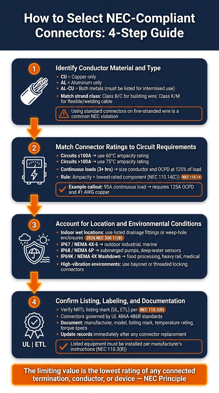
How to Select NEC-Compliant Connectors: 4-Step Guide
Now that you’re familiar with NEC rules for connectors, let’s break down how to apply them effectively.
Step 1: Identify Conductor Material and Type
First, determine the conductor material - copper, aluminum, or a combination - and its stranded class. Look for the connector’s markings. A "CU" label means copper only, "AL" indicates aluminum only, and "AL-CU" allows both metals. However, direct contact between different metals is only acceptable if the connector is specifically listed for intermixed use in dry locations. As Master Electrician Mark Lamendola explains:
"The first requirement is that any connectors (e.g., pressure terminal connectors) must be identified for the material of the conductor. You can't combine dissimilar metals."
The strand class is equally important. Standard connectors work for Class B and C stranding, commonly found in building wire. But if you’re dealing with flexible SO cable or welding cable, which fall into Class K or M (fine-stranded wire), you’ll need a connector designed for those classes. Using a standard connector on fine-stranded wire is a frequent NEC violation that can lead to loose strands and failed inspections.
Once you’ve identified the conductor type, move on to matching the connector’s ratings with your circuit’s requirements.
Step 2: Match Connector Ratings to Circuit Requirements
After determining the conductor type, align the connector’s ratings with the circuit’s electrical needs. According to NEC 110.14(C), the circuit’s allowable ampacity is dictated by the lowest-rated component - whether it’s the connector, conductor, or equipment terminal.
For circuits 100A or less, use the 60°C ampacity rating, even if the wire is rated for 90°C (like THHN). For circuits over 100A, the 75°C rating applies. While the 90°C rating on a conductor can be used as a starting point when accounting for factors like ambient temperature or conduit fill, the final ampacity must not exceed the terminal’s temperature rating.
For continuous loads - those operating for 3 hours or more - both the conductor and overcurrent protection device (OCPD) must be sized at 125% of the continuous load, per NEC 210.20. For instance, a 95A continuous load at 208V three-phase requires a 125A OCPD (95A × 1.25 = 118.75A). Even with 90°C-rated THWN-2 wire, if the terminations are rated 75°C, the conductor size must come from the 75°C column. In this case, #1 AWG copper is required, offering 130A capacity.
Step 3: Account for Location and Environmental Conditions
Next, consider how environmental factors influence connector selection. Moisture is a major cause of connector failure, leading to corrosion, short circuits, and insulation breakdown. For indoor wet locations, the 2026 NEC (Sec. 300.11(B)) mandates the use of raceways with listed drainage fittings or enclosures featuring weep holes.
For outdoor or industrial settings, match the connector’s IP or NEMA rating to the exposure risk:
| IP Rating | NEMA Equivalent | Protection Level | Typical Application |
|---|---|---|---|
| IP67 | NEMA 4X / 6 | Dust-tight; temporary immersion (3.3 ft, 30 min) | Outdoor industrial, marine |
| IP68 | NEMA 6P | Dust-tight; continuous submersion | Submerged pumps, deep-water sensors |
| IP69K | NEMA 4X (Washdown) | Dust-tight; high-pressure/high-temp jets | Food processing, heavy rail, medical |
In high-vibration environments - like those found in rail systems, construction sites, or heavy machinery - opt for connectors with locking mechanisms such as bayonet or threaded couplings to prevent seal failure. For rooftop conduit installations, apply NEC’s ambient temperature adjustments from Table 310.15(B)(4) before finalizing your connector and wire ratings.
Step 4: Confirm Listing, Labeling, and Documentation
Before making a final decision, ensure the connector carries a listing mark from a Nationally Recognized Testing Laboratory (NRTL) like UL or ETL. Wire connectors are primarily governed by UL 486A-486B standards. This mark confirms the product has been tested and meets NEC requirements under Section 110.3(B).
Document the manufacturer, model, listing mark, temperature rating, and torque specifications for every termination point. Proper documentation not only ensures installation quality but also simplifies the inspection process. If you’re sourcing components, platforms like Electrical Trader offer a wide range of listed electrical products, making it easier to find compliant connectors.
Common Connector Types and Their NEC Applications
Different connectors serve specific purposes and must comply with NEC standards, which outline their proper use and limitations.
Twist-On Wire Connectors (Wire Nuts)
Wire nuts are a staple in electrical work for splicing conductors. According to NEC 110.14(B), these connectors must be rated for the exact number and gauge of wires they join. They are effective with solid and standard stranded wires (Class B and C), but they aren't suitable for fine-stranded cables. Using wire nuts on these cables can result in loose strands, potentially leading to inspection failures.
It's also crucial to adhere to enclosure fill requirements outlined in NEC Chapter 9, Table 1.
"Conductor splices must be made inside enclosures per Sec. 300.15. Conductor splices are not permitted inside a raceway, except for wireways per Sec. 376.56." - Mike Holt, NEC Expert
For more durable connections in industrial settings, crimp connectors are often a better choice.
Crimp Connectors and Butt Splices
Crimp connectors are widely used for permanent splices in applications like control wiring, motor leads, and panel terminations. They offer a more secure mechanical connection compared to wire nuts, making them ideal for environments with vibration or frequent movement.
Using the right tools is essential. Always use the manufacturer-recommended tools and dies to avoid hidden damage, and follow specified torque values to meet NEC 110.14(D) requirements.
For flexible cord applications, cord connectors and cable glands provide additional functionality.
Cord Connectors and Cable Glands
Cord connectors and cable glands are designed specifically for flexible cords, ensuring proper strain relief when cables are moved or pass through enclosures. Both NEC and OSHA regulations, including OSHA 1910.305(g)(1)(iii), require these connectors to prevent cord strain from affecting internal terminal connections or splice points.
In wet or outdoor industrial environments, the connectors must be weatherproof, even when a plug is inserted. Additionally, the internal terminations must be compatible with the appropriate strand class.
| Connector Type | Primary NEC Application | Key Requirement |
|---|---|---|
| Twist-On (Wire Nut) | General splicing in junction boxes | Rated for conductor count/size; splices must be inside enclosures |
| Crimp / Butt Splice | Permanent splices, motor leads, control wiring | Match strand class (B/C standard; D/G/H/K/M requires specific identification) |
| Cord Connector / Cable Gland | Flexible cords, machine wiring, panel entry points | Provide strain relief; weatherproof for wet/outdoor locations |
Installation and Maintenance Best Practices
Pre-Installation Checks
Before starting, make sure the circuit is de-energized and locked out. This is a critical safety step. Next, check for any compatibility issues that could impact safety or violate code requirements.
Pay close attention to conductor compatibility and temperature ratings. For example, using copper lugs on aluminum conductors violates NEC 110.14 and can reduce ampacity if even one component is under-rated. You’ll also need at least 6 inches of free conductor at each outlet, junction, or switch point, as required by NEC 300.14. These steps are essential for ensuring a safe and reliable electrical installation.
Post-Installation Verification
Once the installation is complete, double-check that all connections are securely torqued and properly labeled.
"Tighter isn't necessarily better, use the correct torque value. When you tighten to the correct torque value, you obtain maximum clamping power; going past that point dramatically decreases clamping power." - Mark Lamendola, Master Electrician
Always use a calibrated torque wrench to meet the manufacturer's specified torque values, as outlined in NEC 110.14(D). If you’re working with Belleville or split-ring lock washers, tighten them only until the washer is flat - over-tightening can actually weaken the clamping force.
Inspect all connections carefully after torquing. Look for signs of damage, such as exposed strands or compromised insulation. Additionally, make sure all circuits, disconnects, and equipment are clearly labeled with their purpose and ratings. Update panelboard directories with specific descriptions - entries like "lights" or "spare" are not sufficient.
Maintenance and Documentation Over Time
Proper maintenance is just as important as the initial installation. Regular inspections help ensure that the system stays compliant with NEC standards and continues to function safely.
Check connections periodically, re-torque them as needed, and keep documentation current. In damp or wet areas, inspect connectors for corrosion or compromised strain relief. Enclosures in these locations should have at least a ¼-inch air gap from the mounting surface to prevent moisture buildup.
According to NEC 408.4, circuit identification must remain clear and specific - handwritten or faded labels don’t meet this requirement. If a connector is replaced or a circuit is reassigned, update the documentation immediately. For hard-to-find replacement connectors, platforms like Electrical Trader offer options for both new and used components, which can be especially helpful for older industrial systems.
Only qualified personnel should handle connector maintenance, as noted in NEC 110.17. If you’re working with painted enclosures, make sure to remove any nonconductive coating at bonding contact points. This ensures a low-impedance ground-fault current path, as required by NEC 250.110.
Conclusion: Choosing the Right Connectors for NEC Compliance
Following NEC guidelines when selecting connectors is essential for ensuring safety and meeting regulatory requirements. The right connector choice doesn't just prevent immediate issues - it also safeguards the system's long-term reliability. A single misstep, like pairing incompatible conductor materials, using a connector with an inadequate temperature rating, or mismatching components, can lead to high resistance and eventual system failure before any visible signs emerge.
Key factors like material compatibility, temperature ratings, environmental considerations, and proper torque must be prioritized to maintain system integrity. As Mark Lamendola aptly states:
"The limiting value is the lowest rating of any connected termination, conductor, or device. A chain is only as strong as its weakest link."
This principle applies to every connector decision, whether you're matching lugs to specific conductor stranding classes or ensuring IP ratings are appropriate for wet or corrosive environments.
One risk that often goes unnoticed is mixing connectors from different manufacturers. Even if two connectors appear identical, slight differences in dimensions or materials can increase resistance, void warranties, and lead to inspection failures. For example, in solar installations, 83% of projects face connector-related problems, with 3% of those resulting in complete system shutdowns. The same risks apply across various industrial wiring setups.
These challenges highlight the importance of sourcing connectors uniformly and strictly adhering to listed specifications. Keeping accurate documentation - such as photo logs, torque records, and updated circuit directories - further ensures compliance and simplifies future inspections. Always replace connectors with components that meet the same listing and labeling criteria, and make sure records are updated immediately to reflect any changes.
FAQs
How do I know if a connector is listed for my wire type?
To determine if a connector is compatible with your wire type, check the markings or packaging for key details like CU (copper), AL (aluminum), or AL-CU (both). Make sure it aligns with your wire's size, strand class, and ampacity. For fine-stranded conductors beyond class B or C, the NEC mandates specific identification. For more information, refer to the latest UL White Book.
What temperature rating should I size the circuit to?
When sizing circuit conductors, the lowest temperature rating among all components - like terminals, devices, and conductor insulation - dictates the selection. Here's how it works:
- Equipment rated ≤ 100 A: Use the 60°C column from Table 310.16 unless every component in the circuit is rated for 75°C. If all are rated for 75°C, you can use that column.
- Equipment rated > 100 A: Refer to the 75°C column of Table 310.16 for sizing.
You can reference the 90°C column for adjustments such as derating, but the final ampacity must align with the temperature rating of the terminals.
When can a splice be made without a box or enclosure?
Under the NEC, most splices need to be housed in an enclosure, but there are some exceptions. For instance, splices for direct-buried UF or USE conductors that comply with Section 110.14(B) don’t require a box. Other exceptions include listed nonmetallic-sheathed cable interconnectors, wiring methods with removable covers (such as wireways), equipment that has built-in wiring compartments, embedded conductors, manholes, handholes, and cable trays - provided the splices remain accessible.


