
Power Factor Correction Installation: Safety Tips
Power factor correction (PFC) improves electrical efficiency by reducing voltage-current misalignment. It’s crucial for businesses to avoid utility penalties and reduce energy losses. However, installing PFC equipment involves serious risks like electric shocks, arc flashes, and equipment damage if done incorrectly.
Key Safety Tips:
- Pre-Installation Checks: Assess site conditions, check for harmonic distortion (>5% requires detuned reactors), and secure the work area.
- Personal Protective Equipment (PPE): Use arc-rated clothing, insulated gloves, and face shields per NFPA 70E and OSHA standards.
- Qualified Technicians Only: Licensed electricians should handle high-risk tasks and follow lockout/tagout (LOTO) procedures.
- Proper Grounding: Ensure correct electrical connections and grounding to prevent hazards.
- Ventilation: Capacitors generate heat; maintain proper airflow and clean enclosures regularly.
- Inrush Control: Use inrush resistors or reactors to manage current spikes during startup.
- Final Testing: Verify connections, safety features, and system performance before full operation.
By following these guidelines, you can ensure safer installations, avoid equipment damage, and maintain compliance with safety standards.
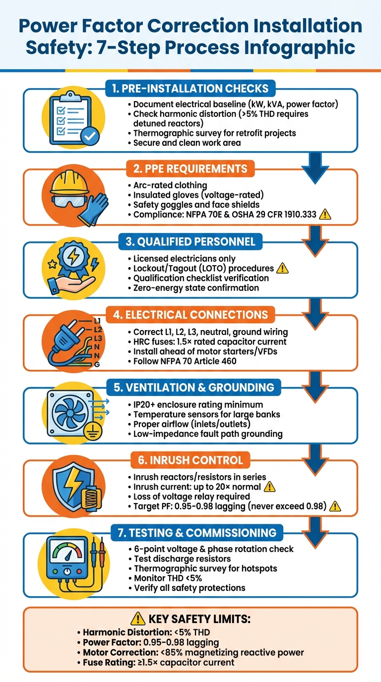
Power Factor Correction Installation Safety Checklist: 7 Critical Steps
Pre-Installation Safety Preparations
Conducting a Site Assessment
Before the equipment arrives, start by documenting the electrical baseline using a power quality analyzer. This tool helps you record key metrics like kW, kVA, and power factor at critical panels, as well as load profiles to pinpoint peak conditions. These steps are essential to ensure the equipment is sized correctly.
Check for harmonic distortions. If the Total Harmonic Distortion (voltage) at the point of common coupling exceeds 5%, fixed capacitor banks could face risks like resonance or overheating. In such cases, opt for detuned filters with series reactors instead of fixed capacitors. Pay attention to equipment like lightly loaded induction motors, welders, arc furnaces, and large HVAC compressors, as they often contribute to a low power factor. Also, inspect the site for hazards like high temperatures, dust buildup, and poor ventilation, as these can reduce equipment lifespan and increase fire risks.
For retrofit projects, thermographic surveys are a must. Use them to check for heat damage on contactors, fuse bases, and copper links before installing any new equipment.
Once you’ve gathered accurate site data, focus on securing the workspace.
Securing the Work Area
Work closely with project and safety leaders to implement the Project Safety Plan before starting any tasks. Make sure cable trenches or supports are properly prepared, painted, and accessible. A tidy and well-organized workspace is essential - not just for efficiency but also for safety, especially when dealing with high-voltage equipment.
Clean the work area thoroughly to eliminate dust-related risks. Perform an arc flash hazard analysis as part of the fault current study, ensuring capacitor discharge paths are considered, as outlined by NFPA 70E and OSHA 29 CFR 1910.333. Limit access to unauthorized personnel and confirm that the power factor correction unit is securely mounted, with all extra bolts, nuts, and washers removed.
With a safe and organized workspace, move on to verifying tools and equipment.
Verifying Equipment and Tools
Before beginning the installation, inspect all tools and equipment, such as power quality analyzers, thermal cameras, and torque wrenches, to ensure they meet the site’s specifications. Double-check that ratings, part numbers, and controller settings align with the electrical requirements.
Make sure all capacitor banks have discharge resistors that can safely reduce touch voltage. For larger capacitor banks, confirm that the area has proper ventilation and that the units are equipped with working temperature sensors.
These steps lay the groundwork for a safe and efficient installation process.
sbb-itb-501186b
Personal Protective Equipment and Technician Requirements
Required Personal Protective Equipment
Once pre-installation checks are complete, it's essential to ensure technicians are equipped with the right personal protective equipment (PPE) and have the qualifications needed for these high-risk tasks.
Power factor correction installations come with serious risks, like arc flash and electrical shock. Capacitors, in particular, can retain energy even after being disconnected. To mitigate these dangers, technicians must wear arc-rated clothing, insulated gloves rated for the working voltage, safety goggles, and face shields when working near energized components or performing live testing. These requirements align with NFPA 70E (2024 edition) and OSHA 29 CFR 1910.333 standards.
For systems operating above 600V, a fault current study - including capacitor discharge analysis - is necessary to determine the correct level of arc flash protection. Additionally, technicians must confirm safe touch voltage using proper meters before beginning any hands-on work.
With these safety measures in place, only qualified technicians should handle the remaining steps.
Qualified Technicians Only
Power factor correction installations demand expertise, especially when dealing with high-voltage switchgear or inspecting internal components. These tasks should only be performed by licensed electricians or qualified duty holders. Technicians need a strong understanding of harmonic analysis, thermographic inspections, and system stability assessments. They should also know when to use detuned reactors instead of fixed capacitors in environments with over 5% total harmonic distortion. Mistakes in sizing or setup can lead to equipment damage and safety risks.
Before starting, use a qualification checklist to confirm each technician's competence for the job.
Qualified technicians must also strictly follow lockout/tagout (LOTO) procedures before beginning any work.
Lockout/Tagout Procedures
Before starting installation tasks, a lockout/tagout (LOTO) process must be implemented, following OSHA 29 CFR 1910.333 and NFPA 70E guidelines. Begin by recording baseline measurements for current, voltage, and VAR/VA readings. Then, apply locks and tags to all disconnects to ensure a zero-energy state.
Capacitors must be fully discharged in line with manufacturer instructions before any contact with components. Additionally, maintain a digital log to document torque settings, component conditions, and "as-found" versus "as-left" states for traceability. Only the personnel who applied the locks and tags should remove them, and only after completing the final verification.
Installation Safety Guidelines
Electrical Connections and Grounding
Once your work area is secure and all safety checks are complete, proper wiring and grounding should be your next priority. Ensure correct connections for L1, L2, L3, neutral, and ground to prevent potential hazards or equipment damage. Follow the guidelines set by NFPA 70 (National Electrical Code), specifically Article 460 for capacitors and Article 430 for motors. The grounding conductor must be sized to provide a low-impedance fault path, which is critical for protecting against electrical shock.
Capacitors should always be installed ahead of motor starters or variable frequency drives to maintain system stability. In medium voltage systems, use a current transformer in the inter star-point connection to monitor for out-of-balance currents, which can indicate internal capacitor failures. Early detection through this method can save equipment from severe damage.
"Arc flash protection systems analysis must account for capacitor discharge paths in the fault current study." - Electrical Trade Network
When selecting fuses, opt for High Rupture Capacity (HRC) fuses rated at a minimum of 1.5 times the rated capacitor current. This safeguards against inrush currents, which can spike to 20 times the normal operating current during initial switch-on. For motor-specific setups, limit capacitor ratings to 85% of the motor's magnetizing reactive power. This precaution prevents self-excitation and dangerous voltage surges when the motor is turned off.
Finally, ensure the system is equipped with proper ventilation and enclosures to mitigate thermal and environmental risks.
Ventilation and Enclosure Safety
Power Factor Correction (PFC) capacitors naturally generate heat during use, so large banks require dedicated ventilation systems and temperature sensors to avoid overheating. Enclosures must meet at least an IP20 protection rating to prevent accidental contact with live components while allowing adequate airflow. Proper placement of air inlets and outlets ensures a steady flow of cool air across capacitor cells and reactors.
Dust buildup can act as an insulator, increasing temperatures and reducing equipment lifespan. Inspect enclosures every three months for signs of overheating, such as bulging, leaks, or discoloration at terminals. Perform a thorough cleaning every 12–18 months and check step contactors for wear or heat damage.
"Clean enclosures; dust raises temperature and shortens life." - CalcPanel
If Total Harmonic Distortion (Voltage) exceeds 5%, detuned reactors are mandatory to prevent harmonic resonance, which can lead to capacitor overheating. This aligns with IEEE 519-2022 standards and is essential for systems with high harmonic content.
Capacitor and Inrush Control Safety
Inrush currents are a serious concern during capacitor installation. To manage these surges, include inrush reactors or resistors in series with capacitor banks. This reduces stress on insulation and minimizes heat buildup during switch-on events.
Use contactors designed for capacitor switching or RC protection modules to prevent burnout. Automatic controllers should feature a "loss of voltage" relay to disconnect capacitors immediately during power interruptions. This step prevents overvoltage conditions when power is restored.
Avoid setting the power factor above 0.98 lagging. Overcorrecting into a leading power factor can cause voltage spikes and relay malfunctions. Additionally, install overvoltage protection to shut down the capacitor bank if the PFC controller malfunctions. This measure protects against severe overvoltage that could damage connected equipment.
Commissioning and Final Testing
Sequential Connection and Testing
With installation wrapped up, it’s time to move into commissioning and testing. Before powering up, double-check that everything aligns with the manufacturer’s drawings and complete all Lockout/Tagout (LOTO) procedures. Inspect all connections, isolation points, and safety measures. Conduct earthing, insulation, and polarity tests, followed by a 6-point voltage and phase rotation check. This step is crucial to prevent controller errors that might result in inaccurate power factor calculations.
Once verified, configure the power factor relay or controller using site-specific data, such as current transformer (CT) ratios and target power factor settings, to ensure smooth operation. Then, manually test each capacitor step to confirm proper connection, disconnection, and cooling fan activation. Record the current and capacitance for each step to ensure they match the unit’s ratings.
Verifying Safety Protections
Before full operation, test all safety features thoroughly. Ensure discharge resistors are effectively lowering touch voltage. Simulate overvoltage and undervoltage conditions to confirm the protection systems are functioning as expected. During initial operation, use thermographic surveys to identify any hotspots on key components like capacitor steps, controllers, fans, isolators, and transformers. Lastly, verify that each bank step has the correct fusing and confirm the breaker/contactor combination works properly.
Monitoring Initial Operation
During the system’s first run, keep a close eye on its performance. Check that the main incomer’s power factor stays between 0.95 and 0.98 lagging under peak load conditions. Ensure feeder currents decrease as expected and that voltage levels comply with local codes. Monitor the power factor over a week to confirm that the automatic switching logic is adjusting correctly to the load profile. If total harmonic distortion (THD) exceeds 5%, consider adding detuned capacitor banks or reactors to prevent resonance issues. Also, avoid overcorrecting to a power factor above 0.98 lagging, as this can lead to voltage increases and relay misoperation.
| Parameter | Target/Limit | Monitoring Method |
|---|---|---|
| Power Factor | 0.95–0.98 lagging | Power meter at main incomer |
| Harmonic Distortion | < 5% THD | Power quality analyzer |
| Voltage Rise | Within local code | Voltmeter / controller display |
| Component Temp | No hotspots | Thermographic survey / IR camera |
| Step Current | Balanced phases | Clamp meter / internal CTs |
Conclusion and Key Takeaways
Summary of Safety Precautions
Installing power factor correction (PFC) equipment requires careful attention to safety protocols at every step. For example, discharge resistors are crucial to reduce capacitor voltage to safe levels before performing maintenance, as residual energy can cause dangerous shocks. PFC capacitors should never be installed on the output side of soft starters or VFDs, as doing so can lead to severe damage to the drive equipment. Proper management of inrush currents with the right switchgear and series resistors is also essential to prevent equipment failure. When total harmonic distortion exceeds 5%, detuned capacitor banks with series reactors are necessary to avoid risks like overheating and resonance. Additionally, avoid overcorrecting beyond a 0.98 lagging power factor, as this can lead to voltage increases, relay issues, and even trips in generators or UPS systems.
Regular maintenance is equally important. Inspect capacitors quarterly for signs of stress, such as bulging or discoloration, and clean enclosures regularly to prevent dust buildup that can elevate temperatures and reduce equipment lifespan. Automatic controllers should include loss of voltage relays to disconnect capacitors immediately during power interruptions. Use HRC fuses rated at least 1.5 times the capacitor current for proper protection. For individual motor correction, ensure capacitor ratings stay below 85% of the motor's magnetizing reactive power to avoid self-excitation and high voltage during shutdown. Following these practices helps protect both personnel and equipment, ensuring reliable and efficient power management.
How Electrical Trader Can Help

By following these essential safety measures, you can achieve a smooth and secure installation process. Electrical Trader supports this effort by offering high-quality, code-compliant PFC components. Their marketplace provides access to new and used equipment, including capacitor banks, automatic controllers, discharge resistors, and protective devices. With products sourced from trusted manufacturers, Electrical Trader ensures compliance with NFPA 70 Article 460 and OSHA 29 CFR 1910.333 standards. Whether you need detuned capacitor banks for environments with high harmonic distortion or automatic switched banks for varying loads, Electrical Trader connects electricians and facility managers with the tools required for safe and effective PFC installations.
Capacitor Bank Installation Considerations
FAQs
Do I need detuned reactors for my PFC bank?
Detuned reactors are a smart choice for power factor correction (PFC) banks when there are substantial harmonics or variable frequency drives (VFDs) in the system. Their primary role is to prevent resonance at harmonic frequencies, which could otherwise lead to equipment damage or inefficiencies. These reactors are usually tuned to a specific frequency - like 189 Hz in 50 Hz systems - ensuring the system operates safely and effectively.
How long can capacitors stay charged after shutdown?
Capacitors can hold a charge even after a system is powered down, which can lead to electrical shock or equipment damage if not properly discharged. The time it takes for a capacitor to fully discharge varies based on the circuit and surrounding conditions. For safety, always assume capacitors are still charged until they are verified as fully discharged.
Where should a PFC capacitor bank be connected in the system?
To effectively improve power factor and avoid utility penalties, a PFC capacitor bank should be installed in parallel. The ideal location is near the service meters or at a point where it can supply reactive power downstream of the utility meter. This placement ensures optimal performance and efficiency.