
IR and PI Testing: Preventing Transformer Failures
Transformer failures are often caused by insulation breakdown, leading to costly downtime and repairs. Regular Insulation Resistance (IR) and Polarization Index (PI) testing can help prevent these problems by identifying issues like moisture, dirt, and aging insulation early. Here's what you need to know:
- IR Testing: Provides a quick snapshot of insulation health by measuring leakage current over 1 minute. Temperature significantly affects results, so adjustments are needed for accuracy.
- PI Testing: Tracks resistance over 10 minutes and calculates a ratio (R₁₀/R₁). A PI value above 2.0 indicates healthy insulation; below 1.0 signals urgent action. Unlike IR, PI testing is less affected by temperature.
- Common Causes of Insulation Breakdown: Thermal stress, moisture, contamination, and mechanical forces reduce insulation strength, leading to transformer damage.
- Benefits of Regular Testing: Early detection of insulation issues allows for scheduled maintenance, reducing the risk of sudden failures, expensive repairs, and operational disruptions.
Key takeaway: Use IR for quick checks and PI for deeper diagnostics. Both tests, when performed regularly, help extend transformer lifespan and ensure reliable performance.
Insulation Resistance & Polarization Index Tests Explained | Transformer Insulation Testing
sbb-itb-501186b
The Problem: Insulation Breakdown in Transformers
Insulation breakdown is one of the leading causes of transformer failure, accounting for over 50% of such incidents. Often, this issue stems from insulation deterioration that goes unnoticed or unaddressed. The insulation system is essential for directing electrical currents along intended paths. When this system fails, the outcomes can range from reduced transformer efficiency to catastrophic events like explosions.
What Causes Insulation to Break Down
Several factors contribute to insulation breakdown, with thermal stress being the most significant. Overloading a transformer or neglecting its cooling system generates excessive heat, which weakens the cellulose insulation. Studies show that for every 10°C (50°F) increase in winding temperature above the rated limit, the lifespan of the insulation is cut in half. The table below highlights how even moderate overloading can lead to significant temperature rises:
| Percentage of Transformer Load | Percentage of Temperature Rise |
|---|---|
| 25% | 20% |
| 50% | 30% |
| 75% | 60% |
| 100% | 100% |
Source: EE Power
Moisture is another major culprit. When moisture enters the system, it reduces the dielectric strength of the insulating oil. For example, while fresh insulating oil typically has a dielectric strength of 40 kV, moisture can lower this to below 10 kV. Virgin insulating oil contains about 50 ppm of moisture, and paper insulation holds roughly 0.5% moisture by weight. As moisture levels rise, the insulation’s ability to withstand electrical stress diminishes.
Contamination also plays a role. Dirt, metallic particles, and oxidation by-products can create conductive paths, leading to partial discharges and shorts. Electrical stress, such as that caused by lightning strikes or switching operations, can exceed a transformer’s Basic Impulse Level (BIL) rating - typically 10 kV for a standard 600-volt unit - resulting in arcing and insulation failure. Mechanical stress from vibrations or short-circuit forces can further displace windings, compounding the problem.
These factors directly impact transformer performance, as outlined below.
How Insulation Failures Affect Transformer Performance
When insulation begins to degrade, transformer performance quickly follows. Elevated heat increases conductor resistance, which leads to higher voltage drops and wasted energy. Damaged insulation allows electrical currents to leak, reducing the transformer’s operational efficiency and capacity. As Taishan Transformer aptly warns:
Once insulation deteriorates, the transformer becomes a ticking time bomb - especially under load or fault stress.
The financial costs of such failures can be enormous. For instance, a 132/33 kV, 63 MVA power transformer failed after six years of operation without proper oil filtration. Moisture levels had risen to 45 ppm, leading to an internal explosion that caused over $900,000 in damages. In another case, a 132/33 kV, 100 MVA transformer, aged 21 years, suffered a catastrophic tank rupture. Investigators linked the failure to accelerated thermal aging and moisture buildup, issues that had been flagged in earlier Dissolved Gas Analysis (DGA) reports but were ignored.
The consequences of severe insulation failures go beyond financial loss. Internal arcing can result in oil venting, tank ruptures, or even fires. Additionally, unplanned outages caused by these failures can disrupt production or lead to regional power blackouts. While transformers are designed to last approximately 20 years under optimal conditions, neglecting insulation maintenance can drastically reduce this lifespan. Regular monitoring with tools like IR and PI tests can identify potential risks early, helping to avoid these costly and dangerous outcomes.
What Are IR and PI Tests?
IR vs PI Testing: Key Differences and Interpretation Guide for Transformer Maintenance
To address the risks of insulation breakdown, accurate diagnostic testing is crucial. Insulation Resistance (IR) and Polarization Index (PI) tests are two key methods used to assess the health of transformer insulation. Both tests involve applying high DC voltage and measuring leakage current, but they focus on different aspects of insulation performance.
Insulation Resistance (IR) Testing Explained
IR testing works by applying DC voltage to the insulation and measuring the resulting leakage current using Ohm's Law. This test, conducted over a one-minute period, provides a quick snapshot of the insulation's condition. It evaluates leakage currents caused by factors like capacitive charging, conduction, surface contamination, and polarization.
For example, in a 220/33 kV, 50 MVA power transformer, the desired minimum IR value at one minute (measured at about 86°F) is around 500 MΩ. Since IR readings are highly influenced by temperature, they typically double for every 18°F decrease. To ensure accurate comparisons over time, it’s important to adjust readings to a standard temperature.
Polarization Index (PI) Testing Explained
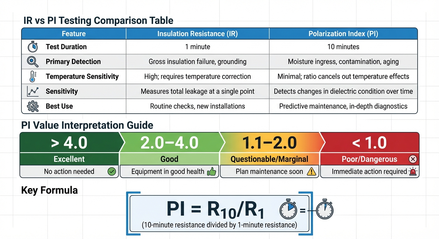
PI testing builds on IR testing by tracking resistance over a longer period. It calculates the ratio of the 10-minute resistance to the 1-minute resistance (PI = R₁₀/R₁). This approach is particularly effective for identifying moisture and contamination within the insulation. As electrical testing expert John Roberts notes:
A PI value above 2.0 generally indicates healthy insulation (dry and clean).
In practice, PI values between 2.0 and 4.0 suggest the equipment is in good condition. On the other hand, values below 1.0 often signal serious insulation issues that require immediate attention. Since both measurements are taken under the same conditions, the ratio helps cancel out temperature effects, making PI testing less temperature-sensitive than IR testing.
How IR and PI Testing Differ
Although both tests measure insulation resistance, they serve different purposes. IR testing provides a quick overview of the insulation's condition, making it ideal for routine checks or newly installed equipment. PI testing, however, examines how the insulation behaves over time, making it better suited for detecting issues like moisture, contamination, or aging - especially in older transformers with paper or composite insulation.
| Feature | Insulation Resistance (IR) | Polarization Index (PI) |
|---|---|---|
| Test Duration | 1 minute | 10 minutes |
| Primary Detection | Gross insulation failure, grounding | Moisture ingress, contamination, aging |
| Temperature Sensitivity | High; requires temperature correction | Minimal; ratio cancels out temperature effects |
| Sensitivity | Measures total leakage at a single point | Detects changes in dielectric condition over time |
| Best Use | Routine checks, new installations | Predictive maintenance, in-depth diagnostics |
Understanding these differences is key to choosing the right test for your maintenance needs. While IR testing is perfect for quick assessments, PI testing offers deeper insights, helping to identify and address potential issues before they lead to costly transformer failures.
How These Tests Prevent Transformer Failures
Regular Insulation Resistance (IR) and Polarization Index (PI) testing act as an early detection system for insulation problems in transformers. These tests can identify issues like moisture buildup, contamination, and aging long before they develop into major failures. What makes them so effective is their ability to monitor how insulation performs under stress over time, uncovering vulnerabilities that could lead to breakdowns.
PI testing, in particular, provides valuable insights through its resistance buildup evaluation. During the 10-minute test, healthy insulation shows a steady increase in resistance as it accumulates charge. If resistance doesn’t rise significantly, it often points to leakage paths caused by moisture or contaminants - both of which can lead to insulation failure. As Electrical Ampere highlights:
Regular PI testing helps avert catastrophic failures and extend equipment lifespan.
By comparing test results over time, maintenance teams can spot gradual wear and tear. For instance, a PI value dropping from 3.0 to 2.2 over several years could signal water ingress or insulation aging. This kind of trend analysis supports predictive maintenance, enabling operators to plan repairs during scheduled downtime instead of facing unexpected outages. These findings help guide smarter maintenance decisions, as explored in the next sections.
Reading and Understanding Test Results
Accurate interpretation of test results is essential to decide whether a transformer needs immediate maintenance or can continue operating safely. Here’s a quick breakdown of PI values and their implications:
| PI Value | Insulation Condition | Action Required |
|---|---|---|
| > 4.0 | Excellent | No action needed |
| 2.0–4.0 | Good | Equipment in good health |
| 1.1–2.0 | Questionable/Marginal | Plan maintenance soon |
| < 1.0 | Poor/Dangerous | Immediate action required |
When working with standalone IR readings, it’s important to adjust values for temperature to ensure accuracy. For example, a 220/33 kV, 50 MVA power transformer should have a minimum IR value of around 500 MΩ at one minute when corrected to 86°F (30°C).
For a quicker snapshot of insulation health, the Dielectric Absorption Ratio (DAR) test can be used, especially on modern insulation materials. However, PI testing remains the go-to method for older equipment, as it provides more detailed insights. Proper interpretation of these results is critical for planning the next steps, as outlined below.
What to Do Based on Test Results
To keep transformers running smoothly and avoid failures, maintenance actions should align with test outcomes. If the PI value drops below 1.0, immediate action is essential. Transformers in this condition are at a high risk of failure and should be de-energized for further diagnostics, drying, or cleaning.
For marginal PI values (1.1–2.0), schedule maintenance promptly. This might include cleaning terminals and surfaces, addressing moisture issues, and taking steps to prevent further insulation degradation.
It’s also important to document each test's R₁ and R₁₀ values, along with ambient conditions, to track insulation health over time. Monitoring these trends can help identify subtle declines in PI values, providing an early warning of potential insulation problems.
Adding IR and PI Testing to Your Maintenance Schedule
Setting up a regular testing routine is a smart way to catch insulation problems before they turn into expensive failures. The key is balancing how often you test with the resources you have. Many facilities include IR (Insulation Resistance) and PI (Polarization Index) tests in their annual maintenance plans. However, the schedule should be tailored to each transformer's importance and working conditions.
How Often to Test
How often you test depends on how critical the transformer is. For high-priority equipment - like those supporting crucial operations or running in tough environments - a risk-based approach works best. For instance, if a transformer shows a steady decline in PI values over time, you might need to check it quarterly instead of sticking to yearly tests.
On the other hand, transformers that aren't as critical and have a stable history can stick to annual or even biennial testing. Always conduct tests after major events like faults, trips, earthquakes, or transportation, as these can cause internal damage. It's also a good idea to take baseline readings when the transformer is first commissioned. These values serve as a reference point for future comparisons.
Testing Procedure Step by Step
Start with safety first. De-energize the transformer, and follow Lockout/Tagout (LOTO) procedures. Ground the windings for several seconds to discharge any stored energy - remember, transformers can hold dangerous charges even when they're off. Clean the bushings and terminals to remove dust, grease, or moisture that could interfere with your readings.
Before testing, record the oil and winding temperatures. These readings help adjust your results to a standard baseline of 20°C (68°F), making year-over-year comparisons more accurate. For three-phase transformers, connect all high-voltage bushings together and all low-voltage bushings together using proper conductor wire.
Next, set up your megohmmeter correctly. Typically, you’ll connect the high-voltage winding to earth, the low-voltage winding to earth, and measure between the high and low windings. If you're working in a humid environment, use the guard terminal to reduce surface leakage effects. Take the R₁ reading at exactly one minute, then continue applying voltage for 10 minutes to get the R₁₀ value. Modern digital megohmmeters often come with built-in PI/DAR timers to eliminate manual timing errors. Finally, log all data, including R₁ and R₁₀ values, ambient humidity, test voltage, and temperature readings.
Using IR and PI Testing with Other Maintenance Methods
Once you've established a regular testing routine, combining IR and PI tests with other diagnostic methods can improve your maintenance program. While IR and PI tests focus on insulation dryness and cleanliness, other methods like Transformer Turns Ratio (TTR) testing can detect winding issues, and Winding Resistance testing can spot loose connections or corrosion.
For example, if PI values drop but TTR results stay within the 0.5% tolerance, the problem is likely with the insulation rather than the windings. Pairing low PI values with Dissolved Gas Analysis (DGA) or moisture-in-oil tests can help pinpoint whether the issue is in the solid insulation or caused by contaminated oil.
This layered approach aligns with NETA guidelines, which suggest routine maintenance every three to five years, with annual IR and PI checks for critical transformers. By integrating these tests, you can focus maintenance efforts where they're needed most, saving both time and money. Documenting your findings and combining them with other diagnostic tools creates a solid, proactive maintenance plan that boosts transformer reliability and helps prevent failures.
Conclusion
Regular Insulation Resistance (IR) and Polarization Index (PI) testing plays a crucial role in transformer maintenance. These tests help detect early signs of insulation breakdown, allowing you to address problems before they escalate into costly failures. For instance, when a PI value drops below 2.0 or shows a downward trend, it’s a clear signal to plan repairs during scheduled downtime rather than facing unexpected outages.
One of the standout benefits of PI testing is its resistance to temperature variations. While a single IR reading can fluctuate with environmental changes, the PI ratio eliminates these effects, delivering reliable and consistent data. This makes it easier to track trends over time: a high PI ratio signals healthy insulation, while a low PI ratio demands immediate action.
As one expert puts it:
"Transformers fail quietly, then all at once. Condition-based testing identifies moisture, insulation, and mechanical issues early, allowing you to plan repairs instead of incurring downtime." – ABM
The financial upside is undeniable. Avoiding even one catastrophic failure can save thousands - if not more - in repair costs, replacement expenses, and lost productivity. Pairing IR and PI testing with additional diagnostics like Dissolved Gas Analysis (DGA) and oil moisture analysis provides a more complete view of transformer health. This proactive approach not only extends the lifespan of your equipment but also ensures smoother, uninterrupted operations.
FAQs
What test voltage should I use for IR and PI on my transformer?
For insulation resistance (IR) and polarization index (PI) testing, a test voltage of 5 kV is typically applied. For transformers with a rating of 220 kV and above, it’s advised to use a high-voltage insulation tester that operates at 2,500V or 5,000V and provides a minimum output current of 3 mA.
How do I temperature-correct IR readings for trending?
To adjust insulation resistance (IR) readings for temperature, you need to standardize them to a common reference, usually 20°C. This is because resistance varies with temperature - specifically, it doubles with every 10°C drop.
For example:
- If your reading was taken at 30°C, divide it by 2 to align it with the 20°C baseline.
- If the temperature is below 20°C, multiply the reading by the corresponding factor.
This adjustment ensures consistent results, making it easier to track trends and accurately evaluate the condition of the insulation.
What should I do if my PI drops but the IR still looks high?
A decrease in the polarization index (PI) combined with high insulation resistance (IR) could indicate the presence of moisture or contamination within the insulation. It's crucial to perform additional tests to assess the condition of the insulation and address any problems quickly. This proactive approach can help avoid potential transformer failures.