
APFC Panel Components Explained
An Automatic Power Factor Correction (APFC) panel optimizes energy efficiency by maintaining a power factor close to 0.98–0.99. It reduces energy losses (8–15% when the power factor drops below 0.90) and avoids utility penalties, which often apply when the power factor is under 0.95. The system dynamically adjusts capacitor banks to balance reactive power demands, freeing up 20–25% of system capacity and lowering energy costs.
Key Components:
- Power Factor Controller: Monitors voltage, current, and phase angle; calculates reactive power needs; activates capacitor banks.
- Capacitor Banks: Supply leading reactive power to counteract lagging currents caused by inductive loads.
- Switching Devices: Contactors or thyristors connect/disconnect capacitor banks based on load changes.
- Sensing Devices: Current and voltage transformers provide real-time data for precise adjustments.
- Protection Components: Circuit breakers, fuses, and surge protectors safeguard against faults, overloads, and voltage spikes.
How It Works:
- Sensing: Current and voltage transformers measure electrical parameters.
- Control: The controller calculates the power factor and determines the required reactive power.
- Switching: Devices engage or disengage capacitor banks to maintain the target power factor.
- Protection: Safety mechanisms ensure system reliability and prevent damage.
By integrating these components, an APFC panel ensures efficient energy management, reduces costs, and extends the lifespan of electrical infrastructure. Proper maintenance, such as annual capacitor checks and thermal inspections, is crucial for long-term performance.
APFC Panel Power Circuit Explanation in Detail | APFC panel wiring diagram| Capacitor Calculations.
sbb-itb-501186b
Power Factor Controller
The power factor controller serves as the brain of the panel, continuously monitoring voltage, current, and phase angle through Current Transformers (CTs) and Potential Transformers (PTs). By analyzing these parameters, it calculates the real-time power factor. If the power factor dips below the target set by the user - usually between 0.95 and 0.99 - the controller determines the reactive power (kVAR) needed and decides which capacitor steps to activate. Here's a closer look at how it operates and its advanced features.
How the Controller Works
At its core, the controller uses a microprocessor to compare the actual power factor against the desired setpoint in real time. It calculates the required kVAR using this formula:
Required kVAR = kW × tan(cos⁻¹(actual PF) – cos⁻¹(desired PF)).
When there's insufficient reactive power, the controller signals contactors or thyristors to connect the appropriate capacitor banks. The reverse happens when the load decreases or the power factor becomes leading - the controller disconnects capacitors to prevent overcorrection, which could result in voltage spikes and potential damage to equipment.
Modern controllers employ intelligent switching to ensure even usage of capacitor banks, extending their lifespan. For facilities with rapidly changing loads, thyristor-based switching provides near-instantaneous response times, avoiding the mechanical wear associated with traditional contactors. Additionally, the controller monitors key metrics like voltage, current, and frequency, displaying them on a digital interface. Alarm indicators alert users to issues such as capacitor failures or overcompensation. These features are essential for maintaining efficient power factor correction, a primary function of the Automatic Power Factor Correction (APFC) panel.
Controller Features and Technology
Advanced power factor controllers go a step further with features designed for accuracy and integration. They use True RMS measurement to ensure precise calculations, even in environments with distorted waveforms. Many models can manage up to 16 capacitor stages and include RS485 and Modbus communication ports, enabling remote monitoring and seamless integration into Building Management Systems.
To tackle harmonics, these controllers often support detuned reactors, filtering out harmful harmonics that can damage capacitors in systems with non-linear loads. The user interface typically offers programmable setpoints and real-time parameter monitoring through digital displays. Regular calibration ensures the system remains accurate over time.
These advanced capabilities make the power factor controller a vital component for efficient energy management and system protection.
Capacitor Banks
Capacitor banks play a central role in the operation of an APFC (Automatic Power Factor Correction) panel. These devices provide the necessary leading kVAR to counteract the lagging currents caused by inductive loads like motors and transformers. Working in tandem with the controller, they ensure accurate reactive power compensation. When inductive loads draw reactive power from the grid, the current lags behind the voltage. Capacitor banks introduce a leading current, reducing this phase difference and improving the power factor. For most industrial setups, the target power factor typically falls between 0.95 and 0.98.
Design and Ratings
Capacitor banks are designed with flexibility in mind, enabling them to meet varying reactive power demands. They are connected in a parallel configuration to the main busbar, allowing individual capacitor groups to be switched on or off independently. This setup provides adaptability to match fluctuating reactive power needs throughout the day. Capacitor units are commonly available in ratings of 30, 50, or 60 kVAR, while smaller units (ranging from 5 to 25 kVAR) are used for more precise adjustments.
The total capacity of a capacitor bank is determined by the specific reactive power requirements of the facility. For instance, a 500 kW load operating at a power factor of 0.75 would require around 275 kVAR of capacitive compensation to achieve a power factor of 0.95. In facilities with significant harmonic distortion - often caused by equipment like variable frequency drives or welding machines - detuned reactors are added to the system. These reactors, typically rated at 5.67% or 7%, help mitigate harmonic resonance issues.
Staged Capacitor Switching
To deliver reactive power efficiently, the APFC controller manages capacitor banks in stages. For steady loads, it uses electromagnetic contactors, while for rapid load fluctuations, thyristor switches are employed. When the power factor dips below the target, the controller calculates the required kVAR and activates the appropriate capacitor stages. As the load decreases, it disconnects stages to prevent overcorrection, which could lead to voltage spikes or penalties. This staged switching strategy ensures the system provides just the right amount of reactive power, optimizing both efficiency and the lifespan of the equipment.
Switching Devices
Switching devices act as the bridge between the controller and capacitor banks, ensuring the system connects or disconnects capacitor stages based on the reactive power requirements. Their role is crucial in maintaining the balance needed for effective power factor correction. When the power factor dips below the target range of 0.95–0.99, the controller prompts the switches to activate the appropriate capacitor stages. Conversely, when reactive power demand falls, the switches disconnect the capacitors to avoid overcorrection. The choice of switching device depends on the load's characteristics and the speed at which the system must react.
Types of Switches
Electromechanical contactors are the go-to option for industrial APFC panels. They are designed to handle the high inrush currents that occur when capacitors are energized, making them a dependable choice for industrial settings where the load remains relatively steady. When the APFC controller sends a signal, the contactor's coil engages, closing the contacts and connecting the capacitor bank to the busbar.
For applications with rapidly changing loads, thyristor-based switches are a better fit. These solid-state devices offer nearly instant response times, allowing for real-time adjustments to capacitive levels. Unlike contactors, thyristors have no moving parts, which eliminates mechanical wear and ensures durability in environments with constant load fluctuations.
In smaller or budget-conscious setups, electromechanical relays may be used. While they are a simple and cost-effective option, their slower response times compared to contactors or thyristors limit their use to less demanding scenarios.
Choosing the right type of switch is essential, but managing inrush currents is equally important for the system's longevity and reliability.
Managing Inrush Currents
Capacitors can draw inrush currents that are several times higher than their normal operating current, potentially causing damage to contacts if not properly managed. To address this, contactors in APFC panels are specifically built to handle these surges, ensuring safe and consistent performance over many switching cycles.
APFC controllers also help by activating capacitor banks in a sequential manner, reducing the strain on switching devices. Additionally, integrating protection devices like fuses or circuit breakers into the system safeguards against overvoltage and faults during switching. This careful coordination of switching and inrush current management is a key part of the panel's broader protection and monitoring system. Together, these measures ensure smooth operation, precise control, and long-term reliability for the APFC panel.
Sensing and Monitoring Components
Sensing components act as the critical input tools for an APFC panel, capturing real-time data to ensure capacitors switch at the right moments. Current transformers (CTs) reduce high line currents to manageable levels for the controller, while voltage sensors (often referred to as potential transformers) measure the system voltage. By working together, these devices enable the controller to calculate the phase difference between voltage and current - an essential factor in assessing your actual power factor. This seamless flow of information ensures the controller can make precise, real-time adjustments.
Why Accurate Measurements Matter
Getting accurate readings isn’t just a technical requirement - it’s a necessity. Inaccurate data can lead to reactive power miscalculations, potentially triggering financial penalties or putting unnecessary stress on equipment. Overcorrection is another risk, which can create a leading power factor. This, in turn, might cause voltage rises that could harm sensitive devices. To avoid such issues, it’s crucial to size sensing components based on real measured load data instead of relying solely on nameplate ratings.
Main Sensing Devices
The APFC relay plays a central role by processing inputs from CTs and voltage sensors to detect when the power factor falls below the desired threshold - commonly set at 0.98 or 0.99. These sensing devices continuously monitor current, voltage, and energy consumption, with multi-function meters providing operators with real-time insights into system performance. For environments with non-linear loads, controlling harmonic distortion is essential to prevent resonance and protect capacitors from damage. Furthermore, in dynamic load conditions - like production lines starting or stopping - sensing devices must respond instantly, enabling the controller to adjust capacitor stages without delay. This level of precision ensures the system can handle rapid changes effectively, maintaining optimal performance.
Protection and Safety Components
After precise sensing and monitoring, the next line of defense is the protection system, which ensures the safety and reliability of the APFC panel and the broader electrical setup. These protective devices guard against faults, overloads, and voltage spikes. Without them, a single issue in one capacitor bank could trigger a domino effect, potentially damaging the entire system. These safeguards operate in layers, starting at the main incomer and extending to individual capacitor stages, isolating faults quickly and effectively.
Circuit Breakers and Fuses
Air Circuit Breakers (ACB) play a vital role in protecting the main incomer by managing incoming power and shielding the busbar. For individual capacitor banks, Molded Case Circuit Breakers (MCCB) and Miniature Circuit Breakers (MCB) provide targeted protection against overloads and short circuits. Additionally, High Rupture Capacity (HRC) fuses offer rapid short-circuit protection for each capacitor step. These devices work seamlessly with the controller's intelligent switching, ensuring faults are isolated without delay. Protective relays, such as over-voltage, under-voltage, and thermal protection relays, continuously monitor critical parameters and disconnect the system if conditions exceed safe thresholds.
Surge Protection and Cooling Systems
Surge protectors defend sensitive components from transient overvoltages, which can occur in facilities with high harmonic content - common in setups with variable frequency drives or LED lighting. To address potential resonance issues that could lead to overheating, detuned reactors are often employed. Managing heat is equally essential, as excessive temperatures can significantly shorten capacitor lifespans. Cooling fans and proper ventilation systems help maintain safe operating temperatures. Regular thermal inspections are also crucial, as they can detect hot spots early, preventing minor issues from escalating into major failures. This proactive approach helps ensure long-term reliability and protects your investment.
How Components Work Together
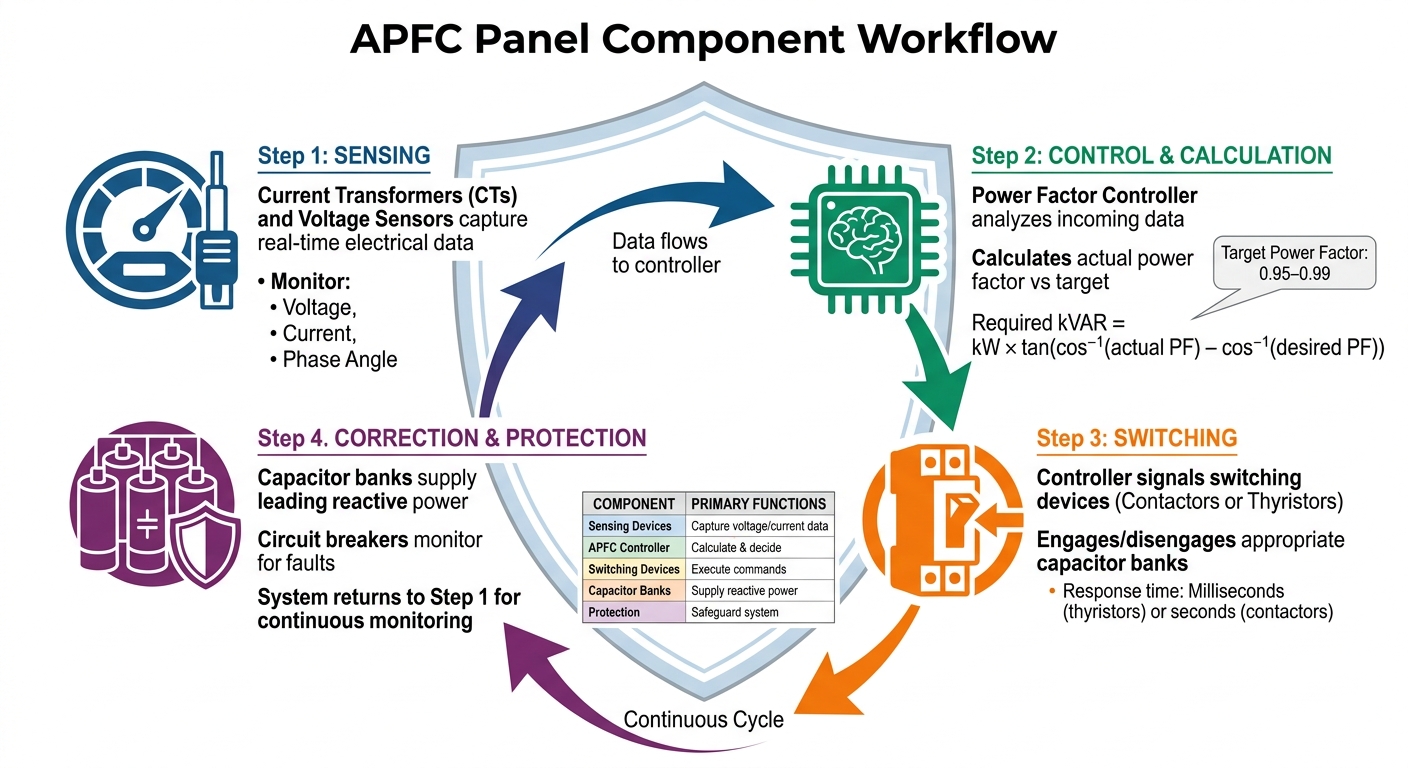
How APFC Panel Components Work Together in 4 Steps
An APFC panel functions as a well-coordinated system, where each component has a specific role in maintaining the desired power factor. The process kicks off with sensing devices - like current transformers and voltage sensors - that continuously monitor electrical data from the incomer section. This real-time data is then sent to the power factor controller, which acts as the system's decision-making hub. From there, the controller processes the information, enabling precise management of the load and power factor adjustments.
Data Flow Between Components
The system relies on the seamless interaction between the controller and the sensors to maintain a steady power factor. The controller’s microprocessor analyzes the incoming voltage and current data to calculate the actual power factor. It then compares this value to a preset target, typically set at 0.98 or 0.99. If the measured power factor falls short of this target, the controller determines the reactive power required to correct it.
Next, the controller signals the appropriate switching devices - contactors or thyristor switches - to engage the necessary capacitor banks. These capacitors then deliver the reactive power needed to improve the power factor. This creates a continuous feedback loop, where the controller reassesses the power factor after each adjustment, ensuring precise capacitor engagement.
| Component | Role in the System |
|---|---|
| Sensing Devices | Capture voltage and current data from the incomer |
| APFC Controller | Processes data, calculates reactive power needs, and sends switching commands |
| Switching Devices (Contactors) | Connect or disconnect capacitors based on controller signals |
| Capacitor Banks | Supply reactive power to correct the power factor |
| Circuit Breakers/Fuses | Protect the system from overloads or short circuits |
Dynamic Load Adjustments
The system doesn’t just make a one-time adjustment; it continuously adapts to changes in demand. APFC panels are designed to handle variable loads, which are common in industrial settings. For instance, during motor starts, stops, or other fluctuating demands, the controller adjusts capacitor stages incrementally. This prevents overcorrection during low-load periods and undercorrection during peak loads.
In environments with rapidly changing loads - like welding machines, elevators, or pressing equipment - thyristor-based switches provide near-instantaneous response times, measured in milliseconds. On the other hand, electromagnetic contactors are better suited for steady, less variable loads. The system’s protection mechanisms also play a critical role in this process. If a circuit breaker detects a fault or an overvoltage condition arises, the controller immediately halts capacitor switching to safeguard the capacitor banks from potential damage.
Conclusion
An APFC panel works best when all its components operate together seamlessly. The power factor controller serves as the system's brain, analyzing real-time data from current and voltage sensors to calculate the exact amount of reactive power needed. Switching devices - whether electromagnetic contactors or thyristor switches - carry out the controller's instructions, activating the appropriate capacitor banks to supply the leading current needed to balance inductive loads. At the same time, protective elements like circuit breakers and surge arresters safeguard the system from faults and overvoltage issues.
This coordinated operation minimizes energy losses and lowers operating expenses. Achieving an optimal power factor not only cuts down on energy waste but also helps avoid penalties from utility providers. Many utility companies charge additional fees if the power factor falls below 0.95, which can lead to a 10–20% increase in electricity costs.
The financial benefits don’t stop at avoiding penalties. An APFC panel system typically pays for itself within 2 to 4 years just through penalty savings alone.
To get the most out of your APFC system, choose switching devices based on your specific load requirements. For fast-changing loads like welding equipment or cranes, thyristor-switched modules are ideal. For steadier, slower-changing loads, electromagnetic contactors are a better fit. If your system experiences high harmonic distortion, consider detuned APFC panels with reactors (5.67% or 7%) to prevent capacitor overheating and extend their lifespan. Regular maintenance is equally important - annual capacitor health checks and thermal inspections can help maintain performance and ensure long-term savings.
When properly configured, APFC panels adapt continuously to changing loads, protect electrical infrastructure, and reduce energy expenses.
FAQs
How do I choose the right kVAR size for an APFC panel?
To determine the right kVAR size, start by measuring your system's current reactive power (kVAR) and power factor. Then, calculate how much compensation is needed to reach a target power factor between 0.98 and 0.99. Select capacitor banks with a total kVAR rating that meets this requirement, ensuring each step aligns with design standards. This approach helps achieve efficient power factor correction while staying within electrical regulations.
When should I use thyristor switching instead of contactors?
Thyristor switching is a great choice for dynamic power factor correction when there's a need for faster, more accurate, and dependable capacitor bank switching. This method shines in systems with rapidly fluctuating loads, where traditional contactors often struggle to keep up.
Do I need detuned reactors if my facility has VFDs or other harmonic loads?
If your facility uses VFDs (Variable Frequency Drives) or other equipment that generates harmonic loads, detuned reactors are a smart choice. These reactors help minimize harmonic distortion, which can otherwise disrupt the performance of your power factor correction system. By keeping harmonic interference in check, detuned reactors ensure your system operates smoothly and efficiently.


