
Ampacity Calculation Tips for Medium Voltage Cables
Medium voltage cable ampacity calculations are essential for safe and efficient electrical systems. Here's what you need to know:
- Ampacity is the maximum current a conductor can handle without overheating. NEC standards, particularly Article 311, guide these calculations.
- Factors like ambient temperature, burial depth, soil thermal resistivity, and conductor proximity affect ampacity.
- Use NEC tables for standard conditions but adjust for deviations using methods like Neher–McGrath or software tools.
- MV-90 and MV-105 cables differ in temperature ratings and ampacity, with MV-105 offering higher capacity but at a higher cost.
- Manufacturer datasheets and advanced modeling tools help refine calculations for non-standard setups.
Key takeaway: Proper ampacity calculations prevent overheating, protect insulation, and ensure long-term reliability. Always plan for future load growth and verify calculations against installation conditions.
Calculating M.V Cables Ampacity inside a Tunnel Using MATLAB

Standards and Reference Materials for Ampacity Calculations
The 2020 National Electrical Code (NEC) brought much-needed clarity to medium voltage (MV) requirements by consolidating them into Article 311. This change unified ampacity tables and installation rules, which were previously scattered across Articles 310 and 328. Now, Article 311 serves as the go-to resource for MV cables operating between 2,001 and 35,000 volts. By centralizing these guidelines, the process of selecting and adjusting MV cable ampacity has become more straightforward.
Key reference points within Article 311 include Tables 311.60(C)(67) through 311.60(C)(86), which detail ampacity values for copper and aluminum conductors in different configurations, such as isolated in air or directly buried in earth. It's important to note that these tables assume single-point grounding of metallic shields. If your installation involves grounding shields at multiple points, circulating currents can significantly reduce the actual ampacity. For instance, a 2,000 kcmil copper conductor at 15kV might see its ampacity drop from 1,575A (with single-point grounding) to 1,327A (with multi-point grounding). As Southwire highlights in their white paper, "The problem is that there are not correction factors or tables for shields grounded at more than one point in the National Electrical Code® (NEC®) 2020".
When the NEC tables don’t align with your specific site conditions - such as burial depths other than 36 inches, soil thermal resistivity differing from the standard 0.9 K·m/W, or ambient temperatures exceeding 86°F (30°C) - you’ll need to turn to advanced methods like the Neher–McGrath method or specialized software tools. These methods allow for detailed modeling of heat dissipation in unique environments, including situations like cable crossings, Horizontal Directional Drilling (HDD), or multiple circuits in a single duct. Beyond the NEC, additional resources such as IEEE Std 835-1994, ICEA standards, and CIGRE Technical Brochure 880 provide a wealth of ampacity data and modern thermal modeling practices.
NEC Ampacity Tables Overview
The NEC ampacity tables offer quick reference values for standard installation conditions: a thermal resistivity of 0.9 K·m/W and a burial depth of 36 inches. These assumptions are fine for simple projects, but they fall short when your installation deviates from these parameters. Correction factors, provided below each table, are essential for keeping cable insulation within its rated temperature - typically 194°F (90°C) for MV-90 cables or 221°F (105°C) for MV-105 cables.
It’s also crucial to consider terminal ratings, as these can limit cable performance. Always verify the temperature ratings of terminations before finalizing conductor sizes. When calculating for continuous loads, use 125% of the full-load current before consulting the ampacity tables. Manufacturer datasheets, discussed next, can help refine these calculations for greater accuracy.
Using Manufacturer Datasheets
Manufacturer datasheets are indispensable for precise ampacity calculations. They provide detailed cable specifications, including dimensions, shield thickness, and thermal limits. When using ampacity software like CYMCAP or ELEK, inputting these exact parameters ensures your thermal model reflects real-world conditions.
As ELEK notes, "Ampacity ratings taken directly from standards are not accurate. These ratings do not consider the actual construction of your cables or the actual installation conditions".
Validation studies have shown that software-calculated ampacity using manufacturer data often differs by less than 3% from the datasheet values under standard conditions. This level of precision becomes especially important for non-standard installations, such as those with unique burial depths, custom backfill materials, or solar PV trenches where soil surface cooling impacts heat dissipation.
Step-by-Step Ampacity Calculation Process
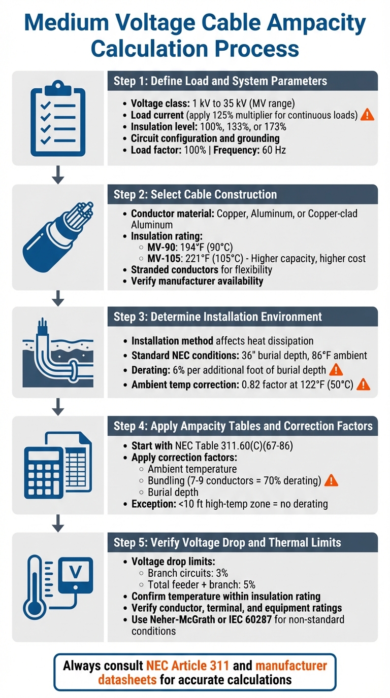
5-Step Medium Voltage Cable Ampacity Calculation Process
Learn how to calculate medium voltage cable ampacity step by step, ensuring compliance with NEC standards and safe thermal limits.
Define Load and System Parameters
Start by outlining your electrical needs. Identify the voltage class, which typically ranges from 1 kV to 35 kV for medium voltage (though ANSI/IEEE standards extend this from 600 V to 69 kV). Determine the load current and whether the system operates continuously or intermittently. For continuous loads, apply a 125% multiplier to the full-load current before selecting a conductor size. This adjustment helps prevent overheating during extended operation.
Next, decide on the insulation level - 100%, 133%, or 173% - based on the ground-fault clearing time of your relay protection. If the relay clears faults in under a minute, 100% insulation is sufficient. For clearance times up to an hour, use 133%. For longer durations or when an orderly shutdown is required, opt for 173% insulation. Consult with your protection engineer for guidance.
"The medium-voltage (MV) cable delivering power must be rated for its voltage level and demand" - Lilly Vang and Joshua Hunter, PE from CDM Smith.
Consider the circuit configuration, including the number of phases, conductors per phase, and whether the conductors are grounded or ungrounded. NEC tables generally assume a 100% load factor and a frequency of 60 Hz.
With these parameters defined, you can select the appropriate cable construction.
Select Cable Construction
Choose the conductor material and insulation rating that align with your load and insulation requirements. Common conductor materials include copper, aluminum, and copper-clad aluminum, each with its own impact on ampacity and cost. Medium voltage conductors are almost always stranded to enhance flexibility.
The insulation type also matters. MV-90 cables (rated for 194°F or 90°C) are widely used, while MV-105 cables (rated for 221°F or 105°C) offer greater current-carrying capacity but come at a higher cost.
Check with manufacturers to ensure availability, as NEC minimum sizes may not always be in stock.
Determine Installation Environment
The way cables are installed significantly affects heat dissipation. Cables in free air dissipate heat more effectively than those in conduits or buried underground.
If your setup deviates from standard NEC conditions, you’ll need to make adjustments. For instance, burying cables deeper than 36 inches requires a 6% ampacity derating per additional foot. Similarly, if ambient temperatures exceed the NEC’s baseline of 86°F (30°C) for underground installations, apply correction factors. For example, at 122°F (50°C) with 90°C-rated insulation, the correction factor drops to 0.82, reducing capacity by 18%.
Once you’ve accounted for these factors, proceed to calculate ampacity using NEC tables and correction factors.
Apply Ampacity Tables and Correction Factors
Start with the base ampacity from the relevant NEC table. Choose the table that matches your conductor material, insulation rating, and installation method. Then, adjust for factors like ambient temperature, bundling, and burial depth.
For example, if you’re bundling seven to nine conductors, reduce the ampacity to 70% of the table value.
"Establishing ampacity ratings is an inexact procedure. For any given situation, these tables should only be used as a starting point when establishing ratings" - AWC Wire.
One exception to keep in mind: if a high-temperature zone spans 10 feet or less and represents no more than 10% of the total cable run, ambient temperature derating is not required.
Verify Voltage Drop and Thermal Limits
After determining ampacity, check the voltage drop. Aim to keep it within 3% for branch circuits and 5% for the total feeder and branch circuit combined. This step is especially important for long cable runs to ensure proper performance.
Finally, confirm that the conductor temperature stays within the insulation’s rated limit. Verify that conductor, terminal, and equipment ratings are not exceeded.
For non-standard conditions, consider advanced engineering methods like Neher-McGrath or IEC 60287 for precise calculations.
sbb-itb-501186b
Tips for Accurate Ampacity Calculations
When it comes to ampacity calculations, real-world conditions can throw in some curveballs. These complexities often make standard calculations less reliable, so it’s essential to account for practical factors to ensure medium voltage cables perform safely in the field. Here’s how to navigate common challenges and keep your calculations precise.
Account for Screen and Sheath Losses
Medium voltage cables don’t just generate heat in the conductor; the metallic screen and sheath layers also contribute. Induced voltages can create circulating currents in these layers, leading to additional heat and, ultimately, reduced ampacity. Standard tables like those from NEC and ICEA assume fixed cable construction, which doesn’t always reflect real-world conditions.
For accurate calculations, refer to manufacturer datasheets. Look for details like screen material (often copper), thickness (around 0.005 inches), and overlap percentage (typically 25%). Factors like lay length (ranging from 1.01 to 1.05) and bonding methods also matter. Single-point bonding can help minimize circulating currents, while cross-bonding tends to increase sheath losses.
"Ampacity ratings taken directly from standards are not accurate. These ratings do not consider the actual construction of your cables or the actual installation conditions." - ELEK Cable HV Software Article
Modern software tools, based on CIGRE Technical Brochure 880 standards, offer more precise ampacity values. These can differ from older ICEA tables by up to 3%, as shown in a case study involving a 25 kV aluminum cable, where differences ranged from 0.76% to 2.88%. For critical installations, this level of accuracy can be a game-changer.
Handle Mixed Installation Conditions
Cables often run through diverse environments - underground, through hot mechanical rooms, or inside conduit banks. Each segment’s unique conditions require separate ampacity calculations. In these cases, the segment with the lowest ampacity governs the entire circuit.
"The ampacities of conductors vary depending on their conditions of use and exposure to surrounding ambient temperatures." - James Stallcup Sr., Author and Code Expert
For installations with varying soil conditions, use the highest soil thermal resistivity value - representing the driest and least conductive soil - to ensure safety margins. If burial depths exceed the standard 36 inches, advanced methods like Neher-McGrath or IEC 60287 can provide more accurate results by factoring in increased thermal resistance.
Plan for Future Load Growth
Designing cables for today’s load alone can lead to future headaches. As systems expand and equipment is added, cables that were once sufficient may become overloaded, risking insulation damage and premature failure.
To avoid this, design with future growth in mind. For instance, consider using MV-105 cables (rated for 221°F or 105°C) instead of MV-90, even if terminations are limited to 90°C. This provides extra thermal capacity for future needs.
In a 2023 case study, engineers designing a water treatment plant in Georgia opted for cables that exceeded the NEC minimum requirements. Although calculations suggested #1 AWG aluminum, the utility specified #1/0 aluminum to reduce voltage drop and standardize the system across dispersed well sites. This approach not only met current needs but also left room for future expansion.
"The ampacity of a cable should equal or exceed the maximum current the cable will be expected to carry during its service life, without exceeding its temperature rating." - Anixter
Using Electrical Trader for Medium Voltage Projects
Once you've nailed down those ampacity calculations, the next step is sourcing the right cables and components. For electricians and facility managers, finding a reliable marketplace is key to securing accurate medium voltage equipment.
Finding Medium Voltage Components
Electrical Trader (https://electricaltrader.com) provides a one-stop platform for sourcing both new and used medium voltage cables, switchgear, and power distribution gear. You can filter products by insulation type - like Tree Retardant Cross Linked Polyethylene (TRXLPE) or Ethylene Propylene Rubber (EPR) - depending on your thermal needs. The platform also organizes items by voltage class (5 kV to 35 kV) and insulation levels (100%, 133%, or 173% IL), helping you match components to your system's specifications.
For challenging environments, consider specialized options like AIRGUARD polymeric-armored cables, which are designed to replace traditional interlocked or continuously corrugated welded (CCW) cables in demanding conditions. If fire safety is a concern - like in densely populated areas or enclosed spaces - Low-Smoke Zero-Halogen (LSZH) cables, such as GenFREE II, are worth exploring. Once you’ve identified potential products, double-check that they align with your ampacity calculations.
Matching Equipment to Ampacity Calculations
After selecting components, it’s crucial to verify that their specifications match your calculated parameters. Manufacturer datasheets are your best friend here - confirm that the cable's diameter, insulation type, and temperature ratings align with your ampacity assessments. Medium voltage (MV) cables should also have durable surface markings showing maximum rated voltage, cable type, manufacturer name, and clear identifiers for conductor size and voltage ratings.
Pay close attention to operating temperatures. Most terminations are limited to 75°C, which can influence overall performance. Additionally, check for markings like "Tray Rated" or "Sunlight Resistant" if your installation demands these features. For setups with more than three current-carrying conductors in a single raceway, remember to apply NEC adjustment factors. For example, if you’re dealing with 4–6 conductors, you’ll likely need to derate to 80% of the base ampacity.
"The medium-voltage (MV) cable delivering power must be rated for its voltage level and demand." - Consulting-Specifying Engineer
Conclusion
Getting ampacity calculations right is crucial for ensuring safe and efficient medium-voltage cable installations. These calculations help prevent overheating, reduce fire risks, and extend the lifespan of equipment. As Lilly Vang, PE, and Joshua Hunter, PE, emphasize: "Although the 2023 edition of NFPA 70: National Electrical Code (NEC) is not a design book, it contains minimum requirements to prevent overheating and fire". Beyond just meeting code requirements, properly sized cables also minimize voltage drops and cut distribution costs, as medium-voltage systems require less current compared to low-voltage setups.
However, accurate ampacity calculations involve more than just consulting standard tables. Factors like ambient temperature, soil thermal resistivity, burial depth, and the number of conductors in a raceway must all be considered to match the actual installation environment.
Planning for future load growth during the design phase is another smart move, as it can help avoid expensive upgrades later. Correctly sized conductors also work as heat sinks, efficiently dissipating heat from device terminals and preserving the overall reliability of the system over time.
To ensure calculations align with real-world conditions, adhere to standards like NEC Article 315 and consider advanced modeling techniques, such as IEC 60287 or the Neher-McGrath method. When it's time to source components, platforms like Electrical Trader (https://electricaltrader.com) can help you find materials that match your specifications and meet compliance requirements.
FAQs
How do ambient temperature and burial depth impact the ampacity of medium-voltage cables?
Ambient temperature and burial depth are key factors that influence the ampacity of medium-voltage cables. Higher ambient temperatures can limit a cable's capacity to carry current effectively. This happens because the heat generated by the conductor combines with the surrounding temperature, potentially leading to overheating. For instance, if the ambient temperature exceeds the typical range of 78°F–86°F, adjustments must be made using a temperature correction factor to ensure safe operation. For buried cables, the soil's temperature also plays a part - warmer soil reduces the current the cable can safely handle.
Burial depth is another critical consideration, as it determines how well heat is dissipated into the surrounding earth. Cables buried deeper generally benefit from improved heat dispersion, which allows for greater ampacity. On the other hand, cables installed at shallow depths may struggle with heat buildup. In such cases, factors like soil thermal resistivity and the type of backfill material used need to be carefully evaluated to maintain safety and performance. Electricians and facility managers should account for these variables when choosing cables for their projects.
If you're in the market for medium-voltage cables or related equipment, Electrical Trader provides a wide selection of products tailored to meet the demands of your specific installation conditions.
What’s the difference between MV-90 and MV-105 medium-voltage cables?
Medium-voltage cables, MV-90 and MV-105, are both designed for voltage ratings between 5 kV and 35 kV. However, they differ in insulation materials, temperature limits, and where they're typically used.
MV-90 cables are built to handle conductor temperatures up to 90°C (194°F) and are insulated with cross-linked polyethylene (XLP). This makes them a solid choice for moderate-temperature settings such as commercial buildings or campus facilities, where cost-effectiveness and reliability are key.
On the other hand, MV-105 cables can withstand higher conductor temperatures of up to 105°C (221°F). They use ethylene-propylene rubber (EPR) insulation, which provides better flame resistance, greater flexibility, and the ability to carry higher currents. These qualities make MV-105 the go-to option for tough industrial environments like chemical plants, steel mills, or facilities with high ambient temperatures.
In summary, go with MV-90 for standard applications in moderate conditions, and pick MV-105 for heavy-duty performance in more demanding settings.
Why should future load growth be factored into ampacity calculations for medium-voltage cables?
Factoring in future load growth is critical to ensuring medium-voltage cables can handle rising electrical demand over time. Ignoring potential increases could lead to overheating or unsafe operation, which might result in system failures or costly upgrades down the line.
Planning ahead for future demand not only helps avoid the expense of re-sizing cables but also ensures compliance with safety standards. Accurate load calculations play a key role in selecting the right cable size, allowing it to meet both current requirements and anticipated energy needs efficiently.


